3. CHAPTER 3
3.1. FLO-2D Storm Drain Data Files
3.1.1. Input and Output File - General
This chapter describes the input and output data and their format for the FLO-2D storm drain component. The storm drain input data files can be created using any storm water user interface GUI. Graphical User Interfaces that can be used to create the stUI options are: FLO-2D QGIS plug-in, GDS, EPA SWMM 5, inpPINS, Autodesk Storm and Sanitary Analysis and Civil 3D Storm and Sanitary Analysis.
The following folders contain the storm drain model system:
FLO-2D PRO folder in C:\Program Files (x86). All executable program files for the FLO-2D model including pre- and post-processing and the FLOPRO.exe are located in this folder.
FLO-2D PRO documentation folder in C:\Users\Public\Documents\FLO-2D PRO Documentation (My Documents). Manuals, Handout Documents, PowerPoint Presentations and tutorials are located in this directory.
3.1.2. Data Input Files
The FLO-2D data input files are generated by the QGIS plug-in or the GDS. The QGIS plug-in creates all the storm drain data files, for more information review the FLO-2D Plugin User’s Manual document. The GDS tool reads the SWMM.inp file (*.INP file cannot be created in GDS) and pairs the inlets with grid elements. GDS creates the associated storm drain data files needed for a FLO-2D Storm Drain simulation (SWMMFLO.DAT, SWMMOUTF.DAT and SWMMFLORT.DAT). Typically, the FLO-2D grid system is prepared prior to developing the storm drain model. The QGIS plug-in or the GDS will generate the files needed to run the FLO-2D Storm drain model. The following data files have to be created to run a FLO-2D storm drain simulation.
3.1.2.1. CONT.DAT
This file contains the simulation control parameters:
Set SWMM = 1 to initiate the storm drain component, review the DATA INPUT MANUAL.DAT file for more information about this switch.
For no storm drain simulation, SWMM = 0 (default).
3.1.2.2. SWMM.inp
SWMM.inp is the input file that contains most of the storm drain project data. It includes pipe network geometry, inlet/outlet and junction locations, simulation control settings and hydraulic routing properties. The pipe network components in the SWMM.inp have to be created with QGIS plug-in or other third-party storm drain software like SWMM GUI. Table 5 lists the section data in the SWMM.inp file. GDS does not create the SWMM.INP file but it reads the file. Each section of the SWMM.inp file begins with a keyword.
Table 5. Sections that Enclose Data in the SWMM.inp (Rossman, 2005)
| [TITLE] | Project title |
| [OPTIONS] | Analysis options |
| [REPORT] | Output reporting instructions |
| [FILES] | Interface file options |
| [JUNCTIONS] | Junction node information |
| [OUTFALLS] | Outfall node information |
| [DIVIDERS] | Flow divider node information |
| [STORAGE] | Storage node information |
| [CONDUITS] | Conduit link information |
| [PUMPS] | Pump link information |
| [ORIFICES] | Orifice link information |
| [WEIRS] | Weir link information |
| [OUTLETS] | Outlet link information |
| [XSECTIONS] | Conduit, orifice, and weir cross-section geometry |
| [TRANSECTS] | Transect geometry for conduits with irregular cross-sections |
| [LOSSES] | Conduit entrance/exit losses and flap valves |
| [CONTROLS] | Rules that control pump and regulator operation |
Rules that control pump and regulator operation
The structure of the SWMM.inp file follows:
Sections appear in any arbitrary order in the input (*.inp) file. Section keywords can appear in mixed lower- and upper-case letters. Only the first four characters (plus the open bracket) are used to distinguish one keyword from another (e.g., [DIVIDERS] and [Divi] are equivalent).
Not all sections must be present on each project.
Each section can contain one or more lines of data.
Blank lines may appear anywhere in the file.
A semicolon (;) can be used to indicate that comment follows, not data. This sometimes generate reading errors in the storm drain code.
Data items can appear in any column of a line.
The data is ordered creating a tabular appearance complete with column headings.
When listing the format of a line of data, mandatory keywords are shown in boldface while optional items appear in parentheses.
A list of keywords separated by a slash (YES/NO) means that only one of the words should appear in the data line.
In the [OPTIONS] section, flow units can be selected as either cubic feet per second (CFS), gallons per minute (GPM), million gallons per day (MGD), cubic meters per second (CMS), liters per second, (LPS), or million liters per day (MLD). If cubic feet or gallons are chosen for flow units then US units are used for all other quantities. If cubic meters or liters are chosen then metric units apply to all other quantities. The default flow units are CFS.
SWMM.inp Example
The typical structure of a SWMM.inp file can be shown as follows:
[TITLE]
INP file created on 10/17/2014 9:30:50 AM by FLO-2D Team Title/Notes:

[OPTIONS]
FLOW_UNITS      CFS
INFILTRATION    HORTON
FLOW_ROUTING    DYNWAVE
START_DATE      03/25/2013
START_TIME      00:00:00
REPORT_START_DATE   03/25/2013
REPORT_START_TIME   00:00:00
END_DATE        03/25/2013
END_TIME        00:24:00
SWEEP_START     01/01
SWEEP_END       12/31
DRY_DAYS        0
REPORT_STEP     00:01:30
WET_STEP        00:01:00
DRY_STEP        00:01:00
ROUTING_STEP    0.05
ALLOW_PONDING   YES
INERTIAL_DAMPING    PARTIAL
VARIABLE_STEP   0.00
LENGTHENING_STEP    0
MIN_SURFAREA    0
NORMAL_FLOW_LIMITED BOTH
SKIP_STEADY_STATE   NO
FORCE_MAIN_EQUATION D-W
LINK_OFFSETS    DEPTH
MIN_SLOPE       0

[EVAPORATION]
;;Type      Parameters
;;---------- ----------
CONSTANT    0.0
DRY_ONLY    NO

[JUNCTIONS]
;;         Invert   Max.    Init.   Surchage    Ponded
;; Name    Elev.    Depth   Depth   Depth       Area
;; ----    ------   ------  ------  ---------   -------
I1CP1C14    1264.35 6.34    0         0          0

[OUTFALLS]
;;         Invert   Outfall    Stage/Table   Tide
;; Name    Elev.    Type        Time Series  Gate
;;-------------- ---------- ---------- ---------- ----
OUTFALL  1254.20    FREE                      NO

[CONDUITS]
;;      Inlet   Outlet          Manning     Inlet   Outlet  Init.   Max.
;;Name  Node    Node    Length     N        Offset  Offset  Flow    Flow
;;-------------- ---------------- ---------------- ---------- ----------
C1      PJ1C1   FOUTFALL  176     0.013       0        0      0     0

[XSECTIONS]
;;Link  Shape   Geom1   Geom2   Geom3   Geom4   Barrels
;;-------------- ------------ ---------------- ---------
C1    CIRCULAR   10       0       0       0       1

[LOSSES]
;;Link  Inlet   Outlet  Average   Flap Gate
;;-------------- ---------- ---------- ---------- ----------

[REPORT]
INPUT   YES
CONTROLS    YES
NODES   ALL
LINKS   ALL

[TAGS]

[MAP]
DIMENSIONS  696350.607  908521.547  697144.791  909040.891
Units   None

[COORDINATES]
;;Node      X-Coord     Y-Coord
;;-------------- ------------------ ------------------
I1CP1C14   696446.346  908983.021

[VERTICES]
;;Link  X-Coord  Y-Coord
;;-------------- ------------------ ------------------
3.1.2.3. SWMMFLO.DAT
A node must have an ID starting with an ‘I’ to differentiate the inlet from a junction. Surface water discharge is only shared between nodes that have the correct ID assigned in the *.inp file. Inlets are automatically paired by the QGIS plug-in or GDS to a corresponding FLO-2D grid element. The SWMMFLO.DAT file contains the inlet geometry as well as the names or numbers that identify the inlet that is paired with the grid cell (Table 6).
Table 6. SWMMFLO.DAT Variables
SWMMFLO.DAT File Variables
Line 1 to Number of Inlets (JT):
SWMMCHAR=‘D’ SWMM_JT(JT) SWMM_IDEN(JT) INTYPE(JT) SWMMlength(JT)
SWMMwidth(JT) SWMMheight(JT) SWMMcoeff(JT) FLAPGATE(JT)CURBHEIGHT(JT)

Notes:
Multiple Inlets (SWMM_IDEN(JT)) assigned to the same grid cell(SWMM_JT(JT)) constitutes a data error.
An Inlet (SWMM_IDEN(JT)) assigned to more than one grid cell(SWMM_JT(JT)) constitutes a data error.
The Table 7 outlines the required data in the SWMMFLO.DAT.
Table 7. SWMMFLO.DAT Input File Example
SWMMFLO.DAT
D 452161 I19CP1SEMDRHRL 1   12  0   0.417  3  0  0
D 451297 I20CP1SEMDRHRL 1   4.8 0   0.417  3  0  0
D 451302 I21CP1SEMDRHRL 1   12  0   0.417  3  0  0
D 450875 I21CP2SEMDRHRL 3   6   4.4 0      3  0  0
D 441072 I22CP1SEMDRHRL 1   12  0   0.417  3  0  0
D 440649 I22CP2SEMDRHRL 3   5   3.0 0      3  0  0
Table 8 lists the variable descriptions for the SWMMFLO.DAT file:
Table 8. SWMMFLO.DAT Input Variable Descriptions
(i) = Integer variable (r) = Real variable (c) = Character
Variable |
Format |
Range |
Description |
SWMMCHAR |
c |
– |
Character Line Identifier |
SWMM_JT(JT) |
i |
– |
Cell Grid paired with the Inlet |
SWMM_IDEN(JT) |
c |
– |
Inlet Name |
INTYPE(JT) |
i |
1, 2, 3, 4 or 5 |
Type of inlet: 1: Curb opening inlet at grade 2: Curb opening inlet with sag 3: Grate (gutter) inlet with/without sag |
4: Unique inlet with stage-discharge rating table 5: Manhole |
|||
SWMMlength(JT) |
r |
0.01- ∞ |
Curb opening length for INTYPE= 1 or 2 Grate perimeter (not including curb side) for INTYPE= 3 For INTYPE = 4 (set to 0 – not needed) Manhole perimeter for INTYPE = 5 |
SWMMwidth(JT) |
r |
0.01- ∞ |
For INTYPE = 1 (set to 0 – not needed) Curb opening sag width for INTYPE=2 Grate open area for INTYPE=3 For INTYPE = 4 (set to 0 – not needed) Manhole flow area for INTYPE = 5 |
SWMMheight(JT) |
r |
0.01- ∞ |
Curb opening height for INTYPE=1 Curb opening height for INTYPE=2 Grate sag height for INTYPE = 3 For INTYPE = 4 (set to 0 – not needed) Surcharge depth for INTYPE=5 |
SWMMcoeff(JT) |
r |
2.8-3.3 |
Recommended weir coefficients are: For INTYPE= 1,3 and 5: Range 2.8 to 3.2 For INTYPE=2: 2.3 For INTYPE = 4 (set to 0 – not needed) |
FLAPGATE(JT) |
i |
0, 1, or 2 |
For INTYPE = 4:
For a fake outfall INTYPE = 1, 2, 3 and 5 can be 0 or 2 |
CURBHEIGHT(JT) |
r |
0.01- ∞ |
Curb height used to calculate discharge on inlets for all INTYPE |
QGIS plugin creates the SWMMFLO.DAT file, review FLO-2D Plugin User’s Manual and FLO-2D Plugin Technical Reference Manual for more information.
To create the SWMMFLO.DAT in GDS, go Tools | Storm Drain | View Storm Drain Inlets Dialog command. Browse for the SWMM.inp file using the GDS Window “Select a Storm Drain *.inp file” as it is shown in Figure 43.
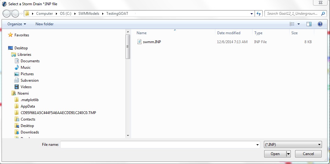
Figure 43. GDS Open *.inp File
The GDS will read the *.inp data file and those junctions which names start with an ‘I’ is identified by the GDS. The data from the storm drain file will then be paired with the data in the SWMMFLO.DAT file. Enter the inlet geometry and save the SWMMFLO.DAT file. The SWMMFLO.DAT file dialog box is shown in Figure 44.
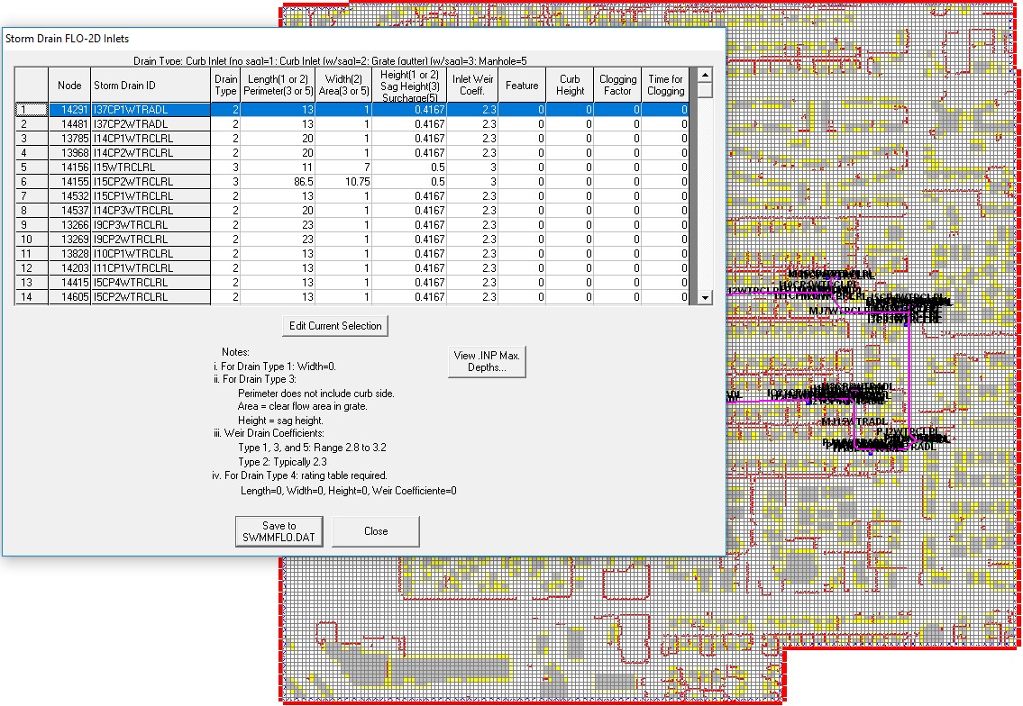
Figure 44. GDS Enter Storm Drain Inlet Geometry Data
The typical structure of a SWMMFLO.DAT file is shown in Figure 45.
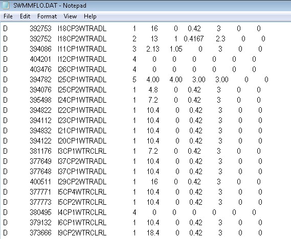
Figure 45. Typical SWMMFLO.DAT Input Data File
3.1.2.4. SWMMOUTF.DAT
This file lists the outfall data, including the name of the outfall, the grid paired with the outfall and the switch (0 or 1) that allow the flow to discharge to the surface or out of the system.
QGIS plugin creates the SWMMOUTF.DAT file, review FLO-2D Plugin User’s Manual and FLO-2D Plugin Technical Reference Manual for more information.
In the GDS, the option to allow the outfall discharge to be returned to the surface water can be selected by checking the ‘Allow Discharge’ box in Figure 46.. This is the ‘Free’ outfall condition. Unchecking the ‘Allow Discharge’ box (‘off’) forces outfall discharge to be removed from the complete model system.
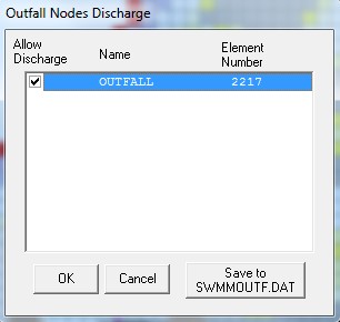
Figure 46. GDS Dialog Box for Storm Drain Outfall Switch
The required data in the SWMMOUTF.DAT is shown in Table 9 and Table 10:
Table 9. SWMMOUTF.DAT Variables
SWMMOUTF.DAT File Variables
Line 1 to Number of Outfalls (JT):*OUTF_NAME(JT) OUTF_GRID(JT) OUTF_FLO2DVOL(JT)
Table 10. SWMMOUTF.DAT Input File Example
SWMMOUTF.DAT File Example
OF1 72565 1OF2 98863 0OF3 97479 1OF4 51882 1OF5 216195 0OF7 382089 1
Table 11 lists the variables and the description for the SWMMOUTF.DAT file:
Table 11. SWMMOUTF.DAT Input Variable Descriptions
(i) = integer variable (r) = real variable (c) = character
Variable |
Format |
Range |
Descriptions |
OUTF_NAME(JT) |
c |
– |
Outfall name |
OUTF_GRID(JT) |
i |
– |
Cell grid paired with the outfall |
OUTF_FLO2DVOL(JT) |
i |
0: off or 1: on |
Allow discharge from the storm drain to FLO-2D |
SWMMOUTF.DAT file should contain the list of outfalls in the same order as it appears on the SWMM.inp. When the outfall order is modified in the SWMM.inp file because an outfall node was added or deleted, the list of outfall nodes in the QGIS plug-in or in the GDS should be edited and the SWMMOUTF.DAT file saved. The functionality of the outfall nodes is as follows:
If the outfall discharge is ‘off’ the outfall will discharge off the complete model system. No discharge is returned from the storm drain to the surface water.
If the outfall discharge switch is ‘on’ the surface water elevation and storm drain pressure head are compared and the outfall will discharge until WSE is equal or greater than the storm drain head. The outfall flow drains back to the surface water.
Potential backflow into the outfall pipe will depend on the comparison of the WSEL, the storm drain pressure head and the tide gate assignment.
3.1.2.5. SWMMFLORT.DAT
The SWMMFLORT.DAT file contains a list of the rating table data only for those inlets that are non-typical inlets assigned as Type 4 in the storm drain system.
QGIS plugin creates the SWMMFLORT.DAT file by automatically reading the rating table from a file for each inlet type 4. For a more detailed information review the FLO-2D Plugin User’s Manual and the FLO-2D Plugin Technical Reference Manual.
In the GDS this option (INTYPE = 4 in the SWMMFLO.DAT) is assigned in the inlet geometry dialog box (Figure 47.). The rating table is used throughout the simulation without adjustment.
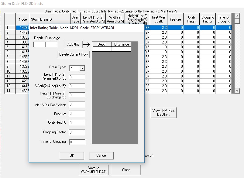
Figure 47. GDS Dialog Box for Entering Rating Table data for INTYPE 4
The structure of a SWMMFLORT.DAT file is:
       ID Grid Cell
       ID Depth Discharge
       ID Depth Discharge
       ID Depth Discharge
       …
The first pair of numbers should be zero depth and zero discharge. This is repeated from 1 to number of storm drain inlets with INTYPE= 4 (Table 12).
Table 12. SWMMFLORT.DAT Variables
SWMMFLORT.DAT File Variables
Line 1 to Number of INTYPE 4 (JTSWMM(JT)):


SWMMCHARRT GRIDCELL SWMMType4ID

SWMMCHARRT DEPTHSWMMRT(JTSWMM(JT),K) QSWMMRT(JTSWMM(JT),K)
The required data in the SWMMFLORT.DAT is listed in Table 12 and Table 13.
Table 13. SWMMFLORT.DAT Input File Example
SWMMFLORT.DAT File Example
D 153076 I4-85

N 0.00 0.00

N 0.70 10.00

N 1.12 20.00

N 1.46 30.00

N 1.77 40.00

N 2.06 50.00

N 2.32 60.00

N 2.57 70.00

N 2.81 80.00

D 199236 I4-196

N 0.00 0.00

N 0.79 10.00

N 1.19 20.00

N 1.56 30.00

N 1.89 40.00

N 2.19 50.00

N 2.47 60.00

N 2.74 70.00
Table 14 lists the description of the variables for the SWMMFLORT.DAT file.
Table 14. SWMMFLORT.DAT Input Variable Descriptions
(i) = Integer variable (r) = real variable (c) = character
Variable |
Format |
Range |
Description |
SWMMCHARRT |
C |
D or N |
D: line with the grid cell paired with the INTYPE 4 N: line with the rating table data |
SWMMType4ID |
c |
– |
Name of Type 4 Inlet |
GRIDCELL |
i |
– |
Cell Grid paired with the INTYPE 4 |
DEPTHSWMMRT(JTSWMM(JT),K) |
r |
0.00- ∞ |
Depth (ft or m) for the rating table |
QSWMMRT(JTSWMM(JT),K) |
r |
0.00- ∞ |
Discharge (cfs or cms) for the rating table |
3.1.2.6. SDCLOGGING.DAT
A clogging factor was created to simulate the debris reduction of the inlet capacity.
QGIS plugin creates the SDCLOGGING.DAT file for inlet type 1,2,3,4 or 5. For a more detailed information about the methodology review the FLO-2D Plugin User’s Manual and the FLO-2D Plugin Technical Reference Manual.
This option (INTYPE = 1,2,3,4 or 5 in the SWMMFLO.DAT) is assigned by the GDS in the inlet geometry dialog box (Figure 48.).
The SDCLOGGING.DAT file contains the data with the following format:
ID  Grid Cell   Inlet ID    Clogging Factor - Cf(%) Time for clogging -Tc(hr)

D   2694           I1           25                              0.50

D   2409           I2           50                              3.25
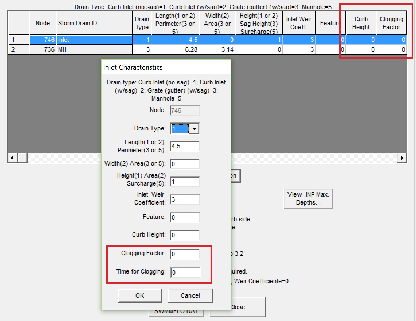
Figure 48. GDS Dialog Box for Entering clogging factor data.
3.1.2.7. SWMM.ini
After a project is saved in the storm drain GUI, the control settings file SWMM.ini will automatically be generated. This file has the same name as the project file and the extension *.ini. It contains global settings and model output options such as map display, legend colors and intervals, object default values, etc. To enable the display of results in the storm drain GUI the user must set the last two lines in Figure 49 as shown.
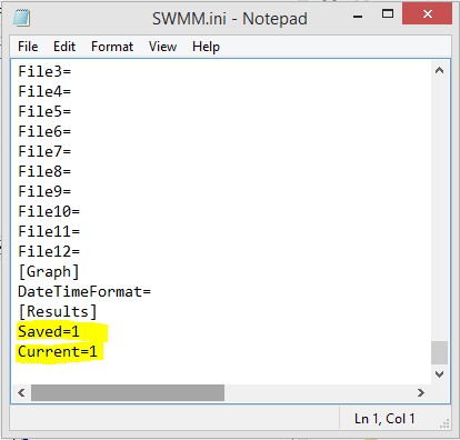
Figure 49. SWMM.ini file.
3.1.3. Output files
With the successful completion of a FLO-2D storm drain simulation, the storm drain output files will be created in the simulation folder. Table 15 list the storm drain output files and the description.
Table 15. List of the Storm Drain Data Output Files and Description
Output File |
Description |
SWMM.RPT |
Output report file generated by the storm drain model at the end of a simulation containing the pipe routing results for each output interval. |
SWMM.OUT |
Output file in a binary format that contains the storm drain results. This file is similar to the SWMM.RPT file and it is used by the SWMM GUI to interactively create time series plots and tables, profile plots, and statistical analyses of the results. |
SWMMQIN.OUT |
Reports the inflow and return flow discharge for each storm drain inlet. The reported discharges may be different from those in the SWMM.RPT file since the storm drain results include lateral pipe inflow and outflow. |
SWMMOUTFIN.OUT |
This file reports the outfall hydrographs for return flow to the surface water system. This file lists the grid or channel element in the first line followed by the time and discharge pairs. |
FPRIMELEV.OUT |
This output file reports the differences in elevation between the rim/invert elevation in the SWMM.inp file and the FLO-2D grid element elevation. This file should be reviewed to evaluate the elevations representing the inlet reference. |
StormDrain_ERROR.CHK |
This output file reports the storm drain error and warning messages. They were removed from the ERROR.CHK file. |
SDManholePopUp.OUT |
This output file reports the information for the manhole popping in the storm drain system. The information reported is: manhole name, time of occurrence, elevation comparison for the popping. |
ManholePop.OUT |
This output file reports the information for the manhole popping in the storm drain system in a table. The information reported is: X coordinate, Y coordinate, grid cell, manhole name, time of occurrence, pressure head, rim + surcharge depth, WSE. |
FPLAIN_SDElev.RGH |
Changes in elevation (FPRIMELEV.OUT) are reported to the FPLAIN_SDElev.RGH file. Replace the FPLAIN.DAT file to apply the changes to the next simulation |
TOPO_SDElev.RGH |
Changes in elevation (FPRIMELEV.OUT) are reported in the TOPO_SDElev.RGH. Replace the TOPO.DAT file to apply the changes to the next simulation. |
UndergOUTFALLS.CHK |
This output file reports the underground outfalls, the invert elevation of the outfall, the grid cell elevation and the difference between them. |
SUMMARY.OUT |
Volume conservation, run time, and final disposition of the volumes between the model components are reported in this file. The storm drain volume is reported as:
Total Inflow - Total Outflow - Total Storm Drain Return Flow - Storm Drain System Storage
|
CHVOLUME.OUT |
This file reports the channel flow distribution including inflow, outflow, overbank flow, infiltration losses and volume conservation. This includes the volumes for channel outflow to the storm drain and channel inflow from the storm drain. |
ERROR.CHK |
This FLO-2D file contains input data error warnings and messages for the surface model. This file should be reviewed for messages after each simulation. |