Overview
The FLO-2D Plugin for QGIS is a tool to develop, format, analyze, and display data used by the FLO-2D Flood Model. The Plugin can import project data, generate data and export appropriately formatted FLO-2D data input files for a FLO-2D Project. This reference manual describes the assumptions, functions, and processes applied in the QGIS Plugin. A companion manual, the FLO-2D QGIS Plugin User’s Manual, describes the workflow, outlines the data structure and presents tutorials for the Plugin. It does not address the functionality and use of the FLO-2D model which has a separate set of reference manuals.
Data File Structure
The FLO-2D QGIS Plugin uses native QGIS layers to display FLO-2D project data. Several aspects of the Plugin file structure are fundamental to understanding project data organization and workflows.
GeoPackage File
All FLO-2D project data is stored in an SQLite database conforming to the GeoPackage specification. The GeoPackage specification is a product of the Open Geospatial Consortium (OGC) and stores spatial data in a non-proprietary database format. For the FLO-2D QGIS Plugin, the GeoPackage file is a *.gpkg file. This file is the central repository for project metadata, spatial information, data layers, and attributes. The Plugin generates and requires a single GeoPackage file for each project.
The GeoPackage file can be perused manually using any compatible SQLite database viewer. Manual editing of the file, however, is not recommended and manual review of the file is not required for the use of the Plugin. Plugin tools process and store data within the project GeoPackage. FLO-2D uses *.dat or *.hdf5 files. These files are exported from the *.gpkg database. Figure 1 shows the layout of the layers and tables in QGIS that are used by the FLO-2D Plugin.
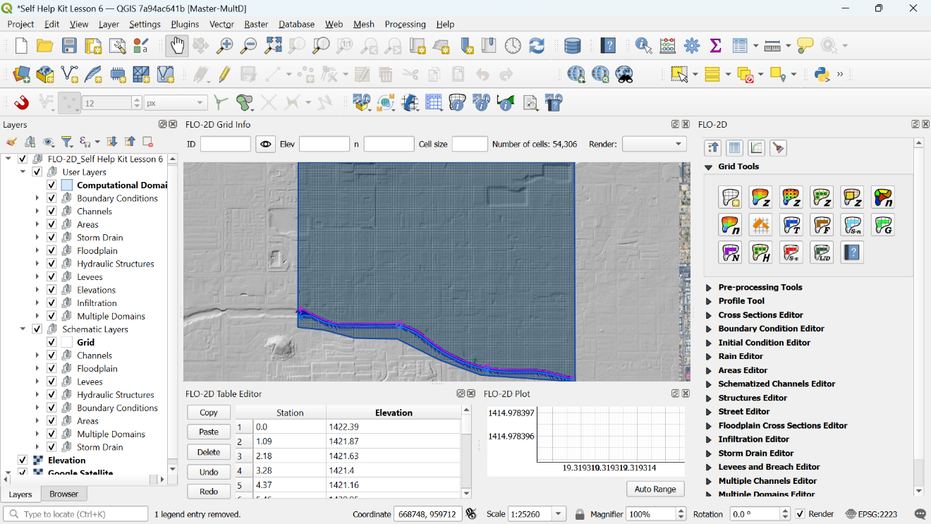
Figure 1. Overview of the QGIS Layout and Layer Structure.
Project Metadata
Non-spatial project metadata, such as data in the CONT.DAT and TOLER.DAT files, as well as the project spatial reference, are stored in tables within the project GeoPackage file. While the project spatial reference is not a spatial dataset, the spatial project data within the GeoPackage file is sensitive to the reference coordinate projection and changes to the selected spatial projection will require regeneration of the project GeoPackage.
Project Spatial Data
Project spatial data is stored within the project GeoPackage file. All input datasets are assumed to have the same spatial coordinate reference system (CRS) as assigned to the FLO-2D project. Datasets in other spatial reference systems should first be projected into the FLO-2D project spatial reference system before attempting to use any of the FLO-2D QGIS Plugin tools.
FLO-2D Plugin
Python Plugin
The FLO-2D Plugin is built with python code. The code is open source and available for any programmer to review or edit. The code is stored in the flo2d directory of the qgis/python/plugins folder (Figure 2).
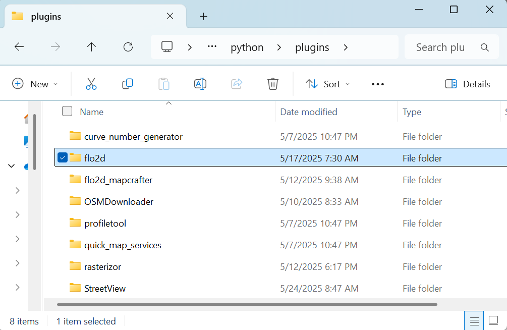
Figure 2. Plugin Folder.
The code can be viewed, queried and edited with any text editor including UltraEdit, Notepad++ or Textpad. The files include the following:
*.png – icon files
*.py – python code files
*.qml – QGIS layer styles
*.svg – icon files
*.sql – SQL code relational database information
*.ui – QT Creator window editor
The plugin is organized into utility-based directories for plugin files that perform specific functions. For example, there is a folder for the toolbar and one for the sidebar widgets. The plugin code is built with Pycharm, and Eclipse. The python formatting module Black is used to format the code. Additional python modules are required for some processing purposes. Numpy, H5PY, HDF5, DASK, and DASK Distributed modules may be installed with the OSGEO4W network installer. This method is more complicated than the stand-alone installer but allows for build updates, and multiple versions. It may be necessary to get IT Admin support to add python modules to the QGIS version of Python.
Plugin Processes
The Plugin builds a GeoPackage file. It is generated by running the FLO-2D Plugin Settings Tool. The GeoPackage contains data to define the layers and tables, create layer styles and views. The Plugin includes all the tools to digitize, import, view, edit and export FLO-2D project data. The processes include:
Import/export tools
Elevation interpolation and adjustment tools
Levee calculation
Sampling spatial data
Schematization
Rainfall interpolation
Infiltration interpolation
Storm drain import, export, digitize
Storm drain SWMM.inp development tools
Channel development tools
Sediment transport and mudflow development tools
HAZUS development tools
Grid System
The grid system is defined by using the extent of the Computational Domain to generate a grid system boundary. The code generates a bounding box using the x (max, min), and y (max, min) of the computational domain polygon. The bounding box aligned to the upper and lower left extent of the computational domain polygon. The cells of the grid are individual polygons ordered by row and column. Only polygons that intersect the Computation Domain layer are created. The default numbering system is in order of row and then column (Figure 3).
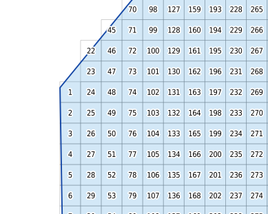
Figure 3. Grid Numbering Scheme.
The Number Units and Coordinate Reference System (CRS) are established when the project GeoPackage is developed using the FLO-2D Plugin Settings Tool. The grid alignment is generally set to the extent of the computational domain, but it can be aligned to the raster as well as shown in Figure 4.
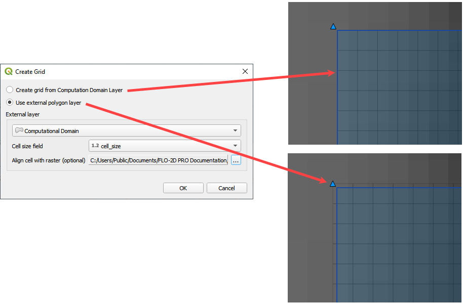
Figure 5. Grid Element Alignment.
Elevation from Raster
The Elevation from Raster calculator uses the alignment and cell size of the grid system to set the origin and raster resolution of the Warp tool. The Geospatial Data Abstraction Library (GDAL) Warp tool is used by the FLO-2D Plugin to generate a temporary elevation file based on one of twelve sampling methods: Near, bilinear, cubic, cubic spline, Lanczos, average, mode, max, min, med, q1 and q3 (Figure 5). The warp is an area weighted calculation of every pixel that touches a single grid element.
After the temporary raster is complete, the grid layer elevation attribute is filled using a centroid point sampling tool. The temporary raster is then removed from QGIS memory, but the interpolate raster is saved alongside the source raster. The external raster layer does not need to have the same coordinates as the project. The warp will transform the new raster into the grid coordinate system. If the elevation layer has the wrong units i.e., meters vs ft, convert the raster to the correct units with the raster calculator before running the elevation from raster processing tool.
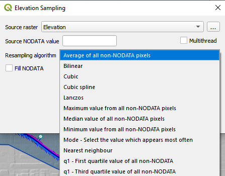
Figure 5. Raster Elevation Dialog Box.
The GDAL warp method is modified so that only the raw input resolution of the raster is applied. This is the most accurate method for the GDAL warp. It is slower than using the ORV data.
Elevation from LiDAR
The Elevation from LiDAR calculator uses a direct average of the points within each cell. (Figure 6).
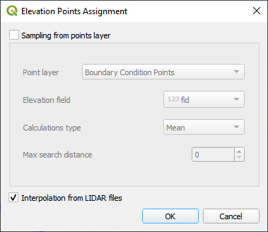
Figure 6. Point Elevation Dialog Box.
If a cell does not contain a point, the cell elevation is averaged from nearest neighbors (Figure 7). The search distance is important if the LiDAR data is filtered from buildings, overpasses, or bridges. LiDAR data for FLO-2D usually represents bare ground. If the Max search distance is too low, there may be a need to process the neighbor calculation more than once. The LiDAR processing tool will identify how many iterations are required to fill the missing grid element elevation. Please remember that there are many excellent LiDAR processing tools available, and this tool is fast and accurate so long as there aren’t too many very large buildings, overpasses, or bridges.
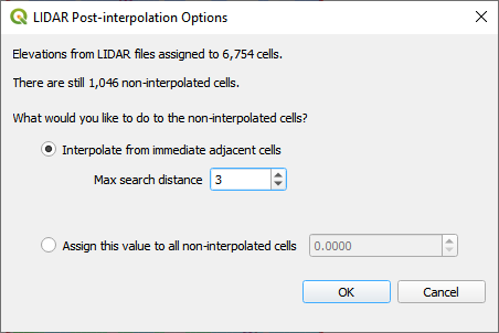
Figure 7. Interpolate Empty Cells Dialog.
Figure 8 shows the elevation interpolation before the missing cell correction, after the missing cell correction and the raster warp.
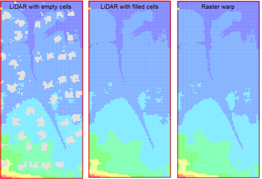
Figure 8. Results Test Case 5.
Elevation Adjustment Tool
The Grid Element Adjustment tool is used to make modifications and corrections to the grid element elevations without having to manipulate the original elevation dataset. It is used to make corrections where the elevation might be assigned incorrectly because of the grid element size. This process can be used to define first floor building elevations, invert elevations at headwalls, inlet rim elevation corrections and channel invert and bank elevation corrections. The Grid Elevation Adjustment tool uses several unique processes to redefine baseline elevation data.
User Layers Mode
The following User Layer corrections are available (Figure 6):
TIN (based on elevation points and polygons)
TIN (based on elevation polygon boundaries)
Elevation polygons attributes
Grid statistics within blocked areas
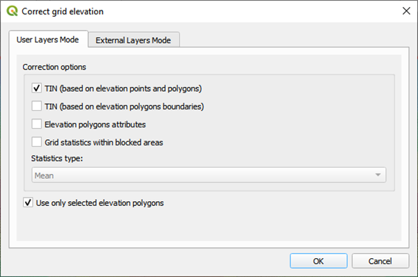
Figure 9. Correct Elevation Dialog Box.
TIN (based on elevation points and polygons)
This method uses a set of elevation points surrounded by triangular irregular network (TIN). The TIN generator is derived from the QgsTINInterpolator feature class that is built in to the QGIS processor libraries. The TIN generator uses the x y coordinates of the elevation correction polygon and the points within the polygon to define the TIN mesh and elevation. The TIN is finally intersected to the grid and the new elevations are assigned to each grid element covered by the TIN.
TIN (based on elevation polygon boundaries)
This method uses a polygon boundary to define a TIN. The TIN generator is derived from the QgsTINInterpolator feature class that is built in to the QGIS processor libraries. The TIN generator uses the x y coordinates of the elevation correction polygon where it intersects to the grid system. The elevations along the boundary of the polygon are used to fill or cut the data from channels or levees. The TIN is finally intersected to the grid and the new elevations are assigned to each grid element covered by the TIN.
Elevation Polygons Attributes
This method intersects the polygon layer to the grid and assigns the elevation or the elevation correction that is defined in the Polygon Attribute Elevation or Correction fields.
Grid Statistics within Blocked Areas
This method intersects the polygon to the grid and calculates the elevation statistics of min, max and mean for each cell within the polygon. The user can select the statistic to use as the final grid element elevation assignment. Each cell within the polygon will be assigned the same elevation.
External Layers Mode
The grid element correction from External Layers Mode offers several methods to correct or edit elevations in the Grid layer from polygon layers that can be imported into the FLO-2D Project in QGIS (Figure 10). The tool uses the same correction calculations discussed above in the User Layers Mode but applies them to imported polygon layers.
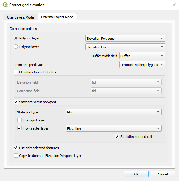
Figure 10. Correct Grid Elevation Dialog Box.
The polygon layer is any polygon layer in the layers list. It can be a layer that is part of the geopackage or an imported shapefile layer. The polygons in the list should cover grid elements that need to be corrected.
The polyline layer can be any external shapefile layer. It requires a buffer field that contains the width of the feature that is being sampled. This could be a ditch or a levee or a gutter. If the buffer width is less than the width of one grid element, the grid element width is sufficient as a buffer width. The polyline can be placed at the center of a feature that needs an adjustment like the ones in Figure 11. The polyline layer is essentially a polygon with the line as a center.
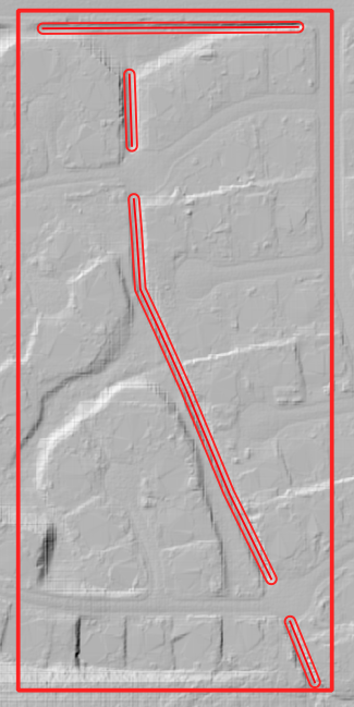
Figure 11. Polyline with Buffer.
The geometric predicate is the intersection method that identifies which grid elements will be adjusted. Grids within polygons means the polygon must cover the whole grid element for the grid element to be corrected. Centroids within polygons are more forgiving and only the centroid of each grid element needs to be within a polygon to be corrected.
The elevation from attributes correction tool applies a direct correction from the elevation and or correction field of the Polygon Layer. The elevation field should contain the new desired elevation in ft or m for the polygon and the correction field should contain NULL or a positive or negative correction value in ft or m. Depending on the geometric predicate, the correction is applied to each grid element or each centroid that falls within the polygon.
The statistics within polygons correction tool uses zonal statistics on wither a group of grid element or a group of pixels that are identified by the polygon. If “from grid layer” is selected, the zonal statistics are applied to the group of grid elements or centroids within the polygon. Each grid element or centroid will get a min, max or mean of the intersected grid elements. If “from raster layer” is selected, the zonal statistics are applied to the raster pixels within the polygon. Each grid element will be assigned a mean, max or min value of raster pixels within the whole elevation polygon. If statistics per grid cell is checked, the raster zonal statistics will be applied to the individual grid elements within the polygon. The checkbox should be used in most cases unless a single elevation is desired for a group of cells.
Levee Tool
The Levee Elevation Tool sees the grid as a set of octagonal sides at a specified distance from the node (Figure 12).
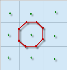
Figure 12. Grid Centroid and Octagonal Sides.
The Levee Elevation Tool uses polylines (Levee Lines) and crest elevation points (Elevation Points) to calculate and digitize the sides of the grid to the Levees layer as “cutoff directions”. The tool uses a combination of polyline to polygon intersection and point to point interpolation to establish the levee position and crest elevation. It intersects each side of the octagon with the Levee Line and a buffer to create individual polylines for each levee cutoff direction as shown in Figure 13.
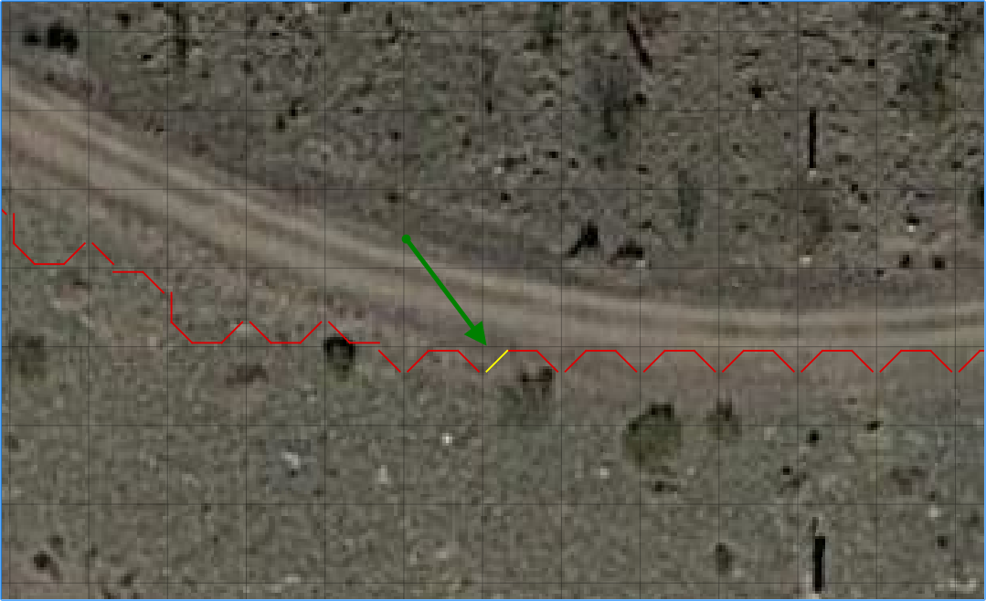
Figure 13. Levee Cutoff Directions.
Walls
The wall calculator is a tool that is used to add polyline data to the Levee Lines (User Layer). This data can represent any levee like feature but was specifically designed to create urban wall features. The wall features are copied from a polyline shapefile with the attributes: crest elevation, correction, and name. The features are copied into the Levee User Layer.
Digitize a wall shapefile to represent the walls that will make a significant impact to the flooding in an urban development. This represents a wall that may prevent flooding in a neighborhood or walls that may cause flooding by blocking water. The depth and velocity vector maps can help identify walls that are hydraulically significant.
Wall Polyline Properties
Walls that have the potential for failure due to collapse should also be identified. The shapefile must have polyline geometry and should have the following attributes:
Name – Feature name (string). The Name field is required by the dialog box, but the values can be null.
Elevation – Crest elevation (ft or m) (real). For walls, this is the top elevation of the wall. This field is required but can be NULL. If NULL, the wall elevation is calculated from the correction field and described in correction as an elevation.
Correction – Elevation correction (ft or m) (real) Null correction is OK.
The correction field is ignored if it is NULL. If Elevation is not NULL and Correction is positive, it will be added to the elevation of the wall.
If Elevation is not NULL and Correction is negative, it will be subtracted from the elevation of the wall.
If Elevation is NULL and Correction is filled, the Correction is used as a wall height and is applied to a wall elevation calculation using the grid max grid element + the wall height.
Figure 14 shows the relationship between a NULL elevation field and a wall height applied to the correction field.
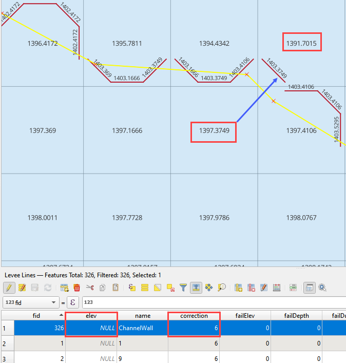
Figure 14. Wall Height vs Wall Elevation.
Wall Failure
The wall calculator is used to assign failure data to the levee polylines. The data required for wall failure is as follows:
Fail Elevation or Fail Depth
Duration (0 default else, duration water is on levee before failure starts)
Maximum Width (0 for wall collapse)
Vertical Fail Rate (0 for wall collapse)
Horizontal Fail Rate (0 for wall collapse)
When a failure depth option is selected, the failure elevation is calculated from the failure depth variable. Once the wall failure is assigned to the Levee Lines (User Layer), the Levee Tool will set up the walls and failure for individual grid elements. Wall failure is complicated due to elevation differences across grid elements. The Levee Tool evaluates the ground elevation on each side of the levee and applies the Failure Depth to the highest grid element. The failure elevation is calculated by adding the failure depth to the highest elevation on either side of the grid element. This condition can be seen on the right-hand side of Figure 15.
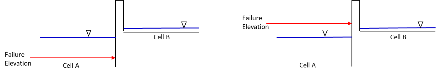
Figure 15. Grid Element Elevation and Wall Failure.
Moving Window Optimization
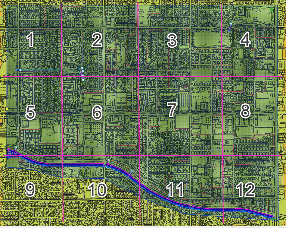
Walls are typically used on large projects and the calculation process can result in too much data for a computer to process. To optimize the plugin, a moving window analysis is used. This window is a geometric bounding box that samples a small set of grid elements at a time. The window size is 100 x 100 grid elements. The levee lines are clipped to the window to eliminate duplicate calculations. Figure 16 shows an example of a grid system split into a bounding box. Each box in the figure is isolated and calculated individually.
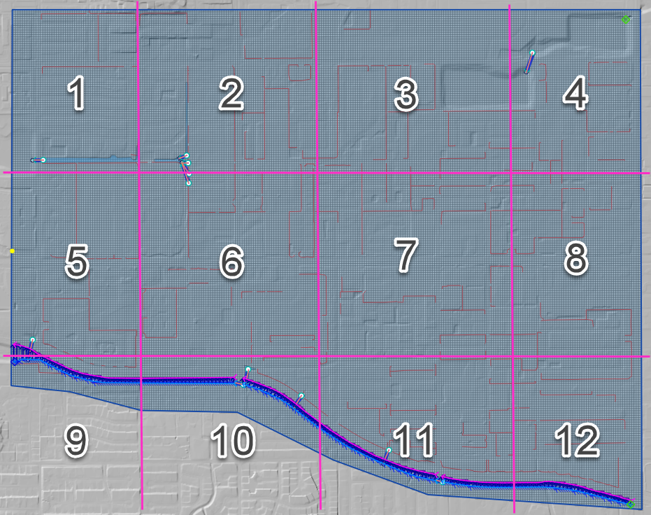
Figure 16. Levee and Wall Moving Window Example.
The final step is to identify and remove duplicates. The levee tables are sorted and scanned for additional duplicates which are removed. Redundant levees are also identified and removed. Duplicate levees are levees with the same cutoff listed twice. That means the same set of D lines for each L line. Redundant levees are levees with a neighboring cell that has a facing levee. They are not typically the same crest elevation. The plugin will identify redundant levees and delete the levee with the lower crest elevation.
Spatially Variable Data Processing
The plugin processes data for several spatially variable data sets. These include:
Manning’s n-value
Spatial Tol (LID)
Spatial Limiting Froude
Spatial Shallow n-value
Gutters
To assign spatially variable data, the Plugin uses a combination of intersecting polygons to the grid and uses the centroid to point sample data to the grid. The spatial data is stored in the attributes table for each polygon. Figure 17 shows an example of a polygon with spatial TOL data. It needs to be assigned to any grid element that intersects the pink polygon. The processor will intersect the pink area to each grid element and extract the grid element number and the TOL variable into a specific layer. In some instances, the intersection is not necessary. A point sample that represents the center of each grid element is used to sample the polygon and extract the data of a known point based on the grid element ID.
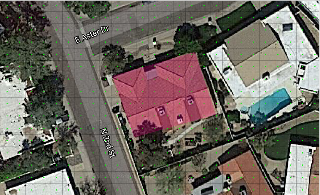
Figure 17. Spatially Variable Data.
Area and Width Reduction Factor
The calculator intersects the polygons in the Blocked Areas (buildings) layer to the polygons in the Grid layer and uses the centroid to set up the ARF/WRF table of variables. The ARF calculator intersects the Blocked Areas polygon with the grid polygon and calculates the area of the building that occupies each grid. If the grid is totally blocked, the ARF = 1. If the blockage is greater than 0.9, the ARF is reset to 1. If the area of the building is a percentage of the grid, then the value is assessed and written to the ARF attribute. Figure 18 shows an ARF that would have a value of 4.74 / 9.29 = 0.51.
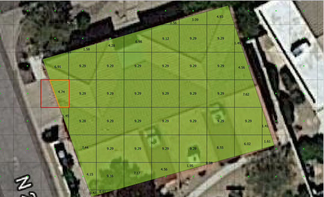
Figure 18. Area Reduction Intersection.
The WRF calculator intersects the Blocked Areas polygon to grid element. It is different in that it intersects the building to the octagonal side of the grid. The WRF calculator uses the grid centroid, half width and a Lambda function (Python, 2018) to define the grid octagon. The Lambda function defines the position of the octagon sides. The octagonal sides are intersected to the polygons in the Blocked Areas layer to calculate the width reduction factor (Figure 19).
Figure 19. Area and Width Reduction Factors.
The QGIS and GDS have slight differences in calculators.
QGIS Method - The Plugin will reset ARF = 1 for any cell greater than 0.90 ARF. This can be seen in the following image. GDS left ARF = 0.94 and QGIS Right ARF = 1 (Figure 20).
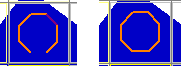
Figure 20. ARF GDS / QGIS Comparison.
GDS Method - The GDS inserts redundant WRFs for cells that would otherwise be empty. This is not necessary and ultimately uses more data. GDS on the left and QGIS on the right (Figure 21).
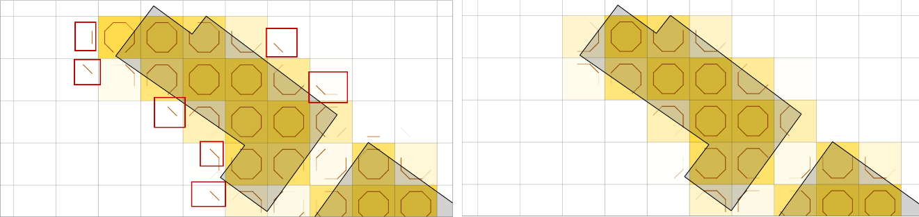
Figure 21. WRF Redundancy GDS / QGIS Comparison.
QGIS calculator is more accurate on cells that have partial WRFs. The GDS WRF on the left is calculated as 0.98. The QGIS WRF on the right is calculated at 0.44 and that is more accurate (Figure 22).
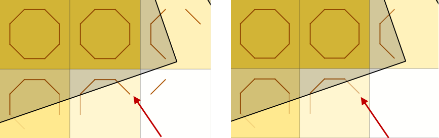
Figure 22. WRF Calculator GDS / QGIS Comparison.
Rainfall Interpolation Tool
The Rainfall Interpolation Tool uses rainfall depth rasters like those provided by NOAA Atlas 14. The original raster resolution is on the order of 2000 by 2000 ft pixels (Error! Reference source not found.).
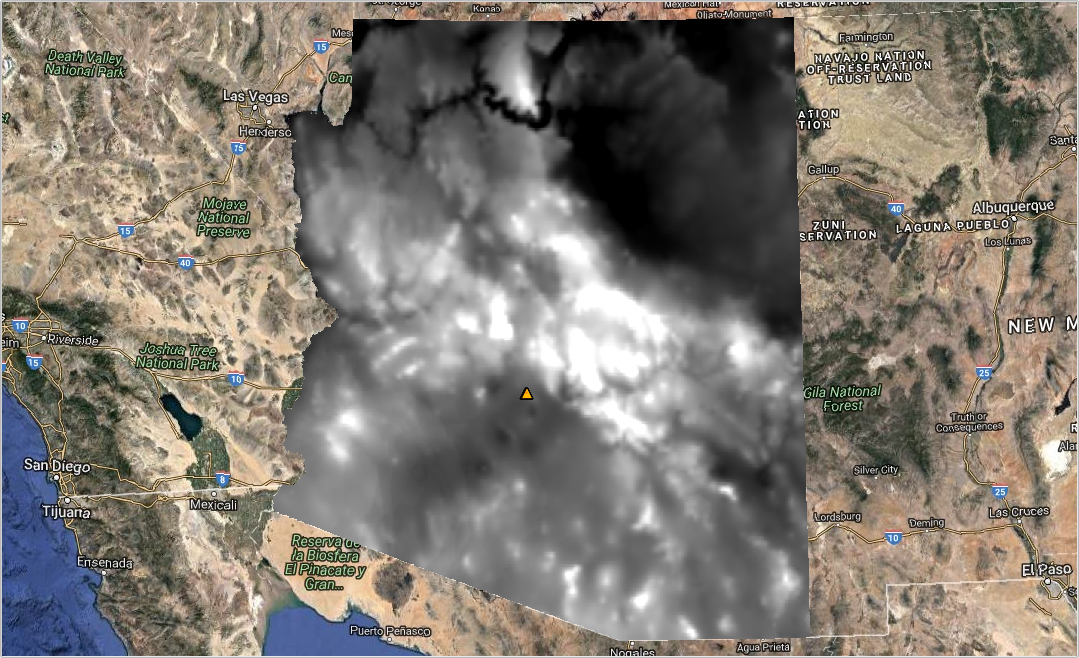
Figure 23. Rainfall 24hr 100yr NOAA Atlas 14.
The interpolation processor performs a GDAL Warp function to build a rastername_interp.tif. The new raster has these properties:
Re-projected CRS = Project CRS.
Pixel size = grid element size.
Clipped to Grid layer extent.
Aligned to the grid.
The new raster (figure 24) is sampled to the grid using the centroid. Raster statistics determine the maximum rainfall value (RAINmax). The final RAINarf variable is calculated as a ratio of the local rain depth to the max rain depth. A rainfall reduction value is calculated for each element in the grid system using equation (1).
Where:
RAINarf = A spatially reduced rainfall value
RAINgrid = The rainfall sampled from the centroid of the grid element.
RAINmax = The maximum rainfall for the raster in the project area.
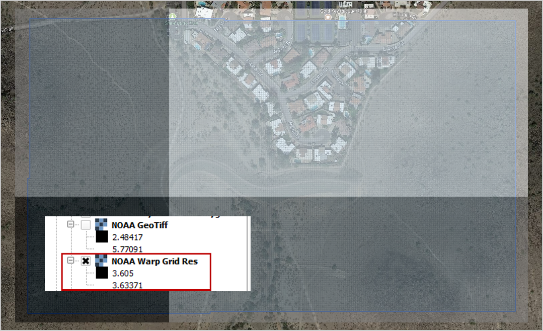
Figure 24. Warped Rainfall Raster.
Real-time Rainfall Sampling Tool (NEXRAD Data)
Interpolated rainfall data from NEXRAD is an estimation of a rainfall event over a particular region using data from the NEXRAD radar network. NEXRAD (Next-Generation Radar) is a network of over 150 high-resolution Doppler weather radars operated by the National Oceanic and Atmospheric Administration (NOAA) in the United States.
The spatial and temporal resolution of the radar rainfall data is limited by the network coverage, and there are gaps and inconsistencies in the precipitation data. The NEXRAD data is post processed or interpolated to rain gage data. The interpolation algorithms analyze the relationship between the radar observations and the topography of the region to estimate rainfall. The interpolated rainfall data from NEXRAD can be used by FLO-2D to simulate real storm events.
The Real-Time Rain Interpolation Tool requires ascii grid files *.asc files and a catalog file *.rtc with the rainfall heading data and list of grid files to import. There is one file for every 5 to 15 minutes of rainfall. Figure 25 shows the layout of a *.asc file and a group of files.
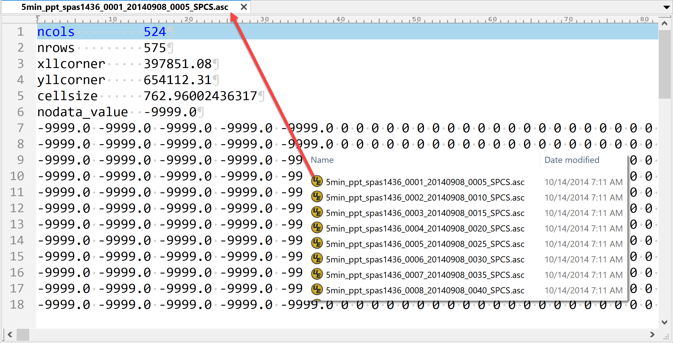
Figure 25. NEXRAD Rainfall *.ASC File Example.
The *.asc files are read as rasters in alphabetical order. Each raster file is warped to the grid and sampled at the centroid as described in the previous section. The grid assignment is a point sample. The data is not interpolated. The plugin will export a RAINCELL.DAT file or a binary RAINCELL.HDF5 file. These files contain the entire rainfall event. Figure 26 shows an example of the rainfall data file.
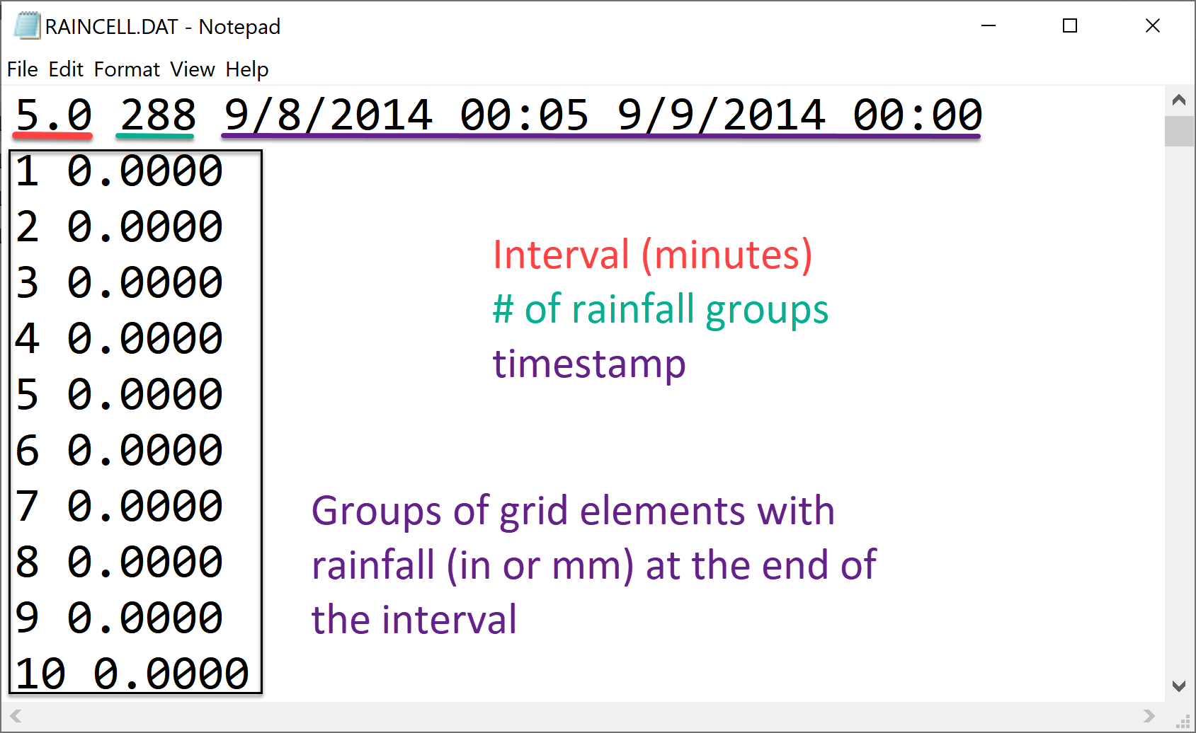
Figure 26. RAINCELL.DAT.
Infiltration Development Tools
The Infiltration Editor is used to assign infiltration data globally or spatially from polygon layers. The Infiltration calculators can use embedded layers for infiltration or imported layers. The infiltration calculators intersect the infiltration polygons to each cell to calculate area weighted infiltration parameters. The infiltration calculator is optimized to run on large projects with millions of cells. The optimization process isolates blocks of polygon data and runs them individually as defined by small bounding boxes that break up the data for processing. Individual calculations are addressed below for each infiltration type.
Green and Ampt
There are various methods for assigning spatially variable Green and Ampt data. The Schematize method assigns data directly to the grid from polygons digitized to the Infiltration Areas layer. The calculator calculates data from external soils and landuse layers.
Schematize Method
The Schematize Method samples the Infiltration Areas polygons from the grid centroid and assigns the infiltration values that are written in the Green Ampt fields. These fields are the fields that are written to the INFIL.DAT file:
green_char – green ampt character
hydc – hydraulic conductivity
soils – soil suction
dtheta – soil moisture deficit
abstrinf – initial abstraction
rtimpf – impervious percentage
soildepth – soil depth
The attribute data is written to the infil_cells_green table. The widget uses the poly2grid processor. This processor uses an intersection where the grid element centroid is located within a polygon in the Infiltration Areas layer. The Green-Ampt attributes for the grid elements are copied to the infil_cells_green table. Any grid element that does not contain a polygon is not written to the table. That infiltration data will default to the Global Infiltration parameters.
Green and Ampt (FCDMC Method 2023)
The Calculate Green and Ampt Method intersects the landuse and soils polygons to the grid polygons and calculates a spatially variable infiltration from the external layers. Figure 27 shows the Compute Green-Ampt dialog for the FCDMC Method 2023.
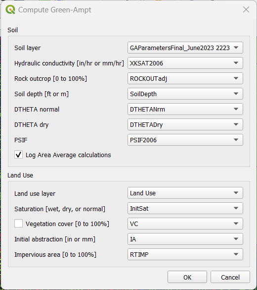
Figure 27. Compute Green-Ampt dialog (Log Average Method 2023)
This method follows the guidelines in the FCDMC Hydrology Manual from 2023 (FCDMC, 2023). The difference between this method and the 2018 method is the Log Average of PSIF. The general calculations are as follows:
XKSAT
XKXAT is the hydraulic conductivity in in/hr or mm/hr of the soil layer. Figure 28 shows the hydraulic conductivity of the soil layer.
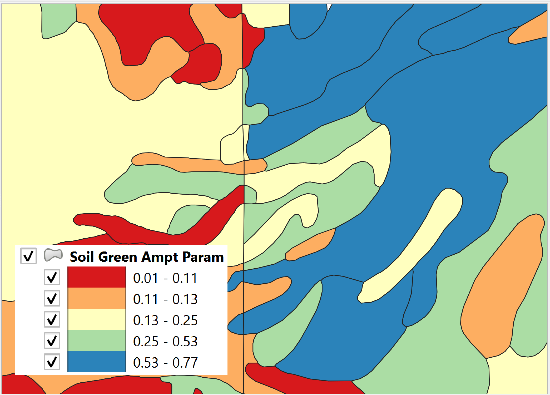
Figure 28. Soil layer with XKSAT.
The area weighted log average is calculated for each grid element from the soil layer equation(2). The soil polygon is intersected with the grid polygon to provide the Ai.
Where:
XKSATi is obtained from the soil attribute table.
Ai is the subarea intercepted by the grid element from the 3rd column of the landuse table and AGE is the grid element area.
PSIF
PSIF is the wetting front capillary suction in or mm of the soil layer (Figure 29).
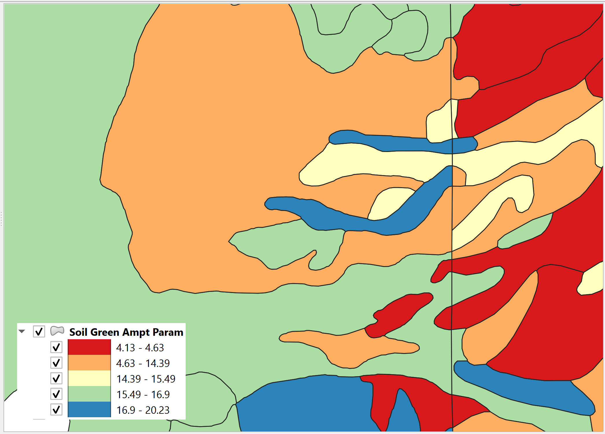
Figure 29 Soil Layer with PSIF.
The area weighted log average is calculated for each grid element from the soil layer equation (3). The soil polygon is intersected with the grid polygon to provide the Ai.
Where:
PSIFi is obtained from the soil attribute table.
Ai is subarea intercepted by the grid element from the 3rd column of the landuse table and AGE the grid element area.
DTHETA
DTHETA is the soil moisture deficit. It ranges in value from zero to the effective porosity of the soil (Figure 30).
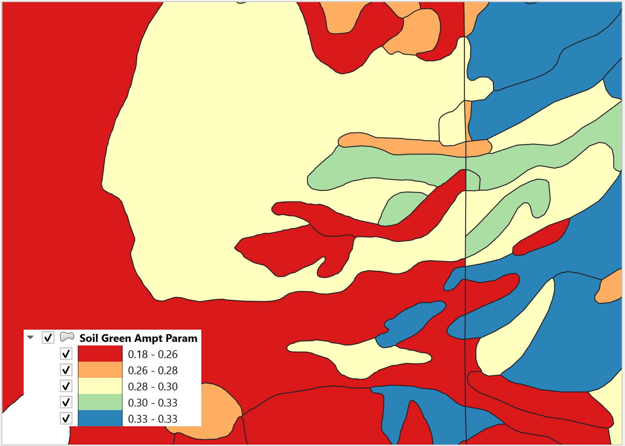
Figure 30 Soil Layer with DTHETA.
DTHETA represents the soil moisture capacity for the start of a rainfall event. The initial soil conditions vary with respect to landuse categories like irrigation or ponded water conditions. Initial saturation is part of the landuse data (see Figure 31).
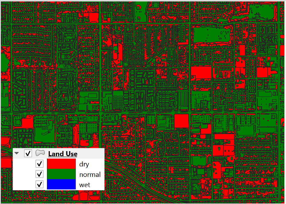
Figure 31. Landuse with Initial Saturation Condition.
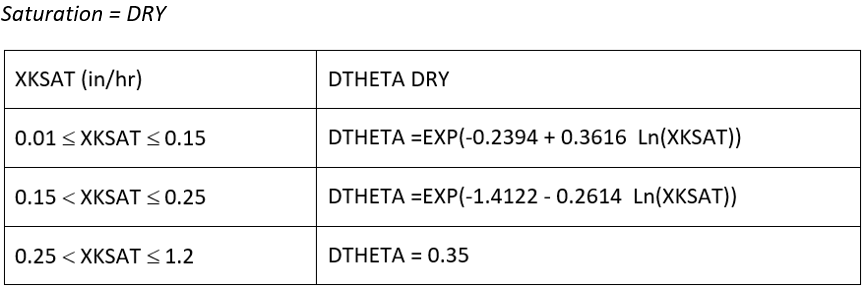
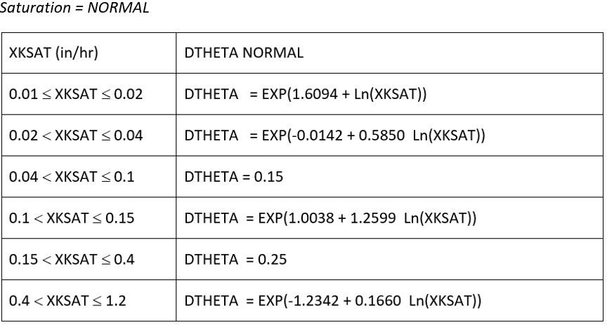
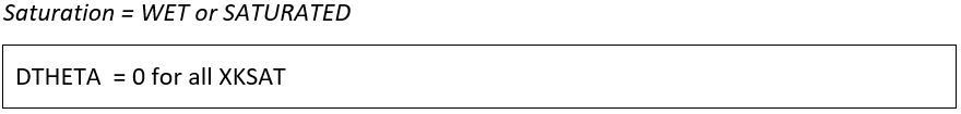
As a result, DTHETA is split into individual parts that represent the DTHETA (wet, dry or normal). DTHETAwet is zero, DTHETAdry and DTHETAnormal are calculated for the soil layers for individual soil groups (Figure 32).
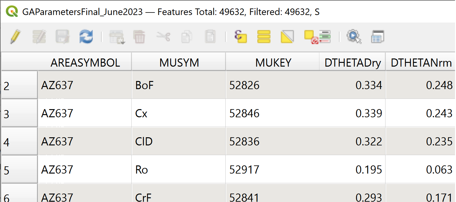
Figure 32. DTHETA Dry and Normal.
After the soil layer is intersected with the landuse, DTHETAparts attributes are filled. DTHETAwet, DTHETAnormal, and DTHETAdry attributes are filled for individual parts. Once DTHETAparts is complete, DTHETAgrid is calculated using a weighted average for each grid element equation (4).
Where:
DTHETAi is taken from the intersected landsoil DTHETAparts.
Ai is the subarea intercepted by the grid element from the 3rd column of the landuse table and AGE is the grid element area.
If a grid element is within by a “wet” or “saturated” polygon, the DTHETA for that grid = 0.
RTIMP
RTIMP is the percent impervious of the landuse (paved surfaces, buildings) and the soil (rockout). Figure 33 shows the rock out percentages for the landuse layer.
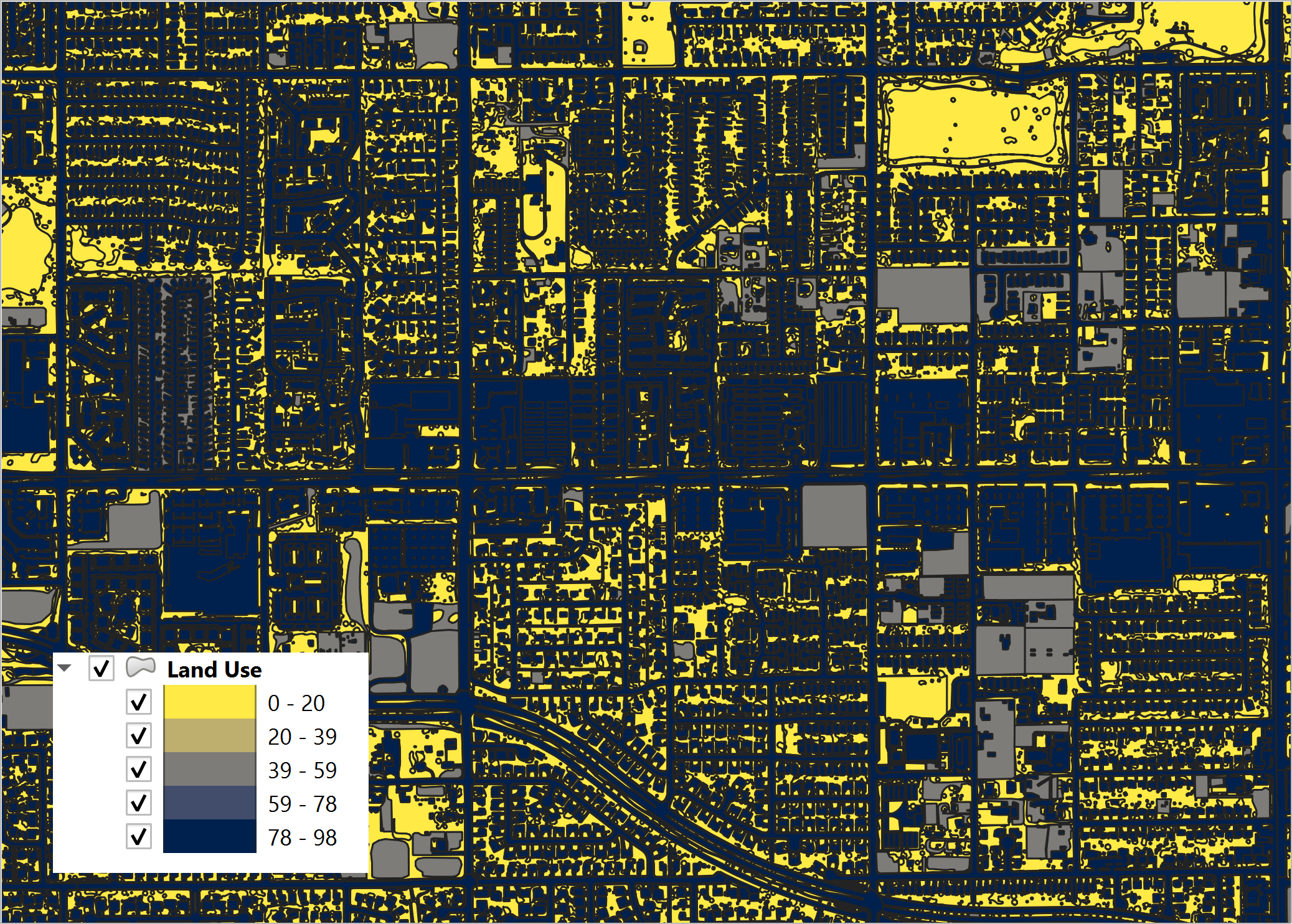
Figure 33. Landuse with Rockout Percentages.
Intersecting the landuse with the soil combines the data into a single layer (land_soil) of polygon features with attributes of RTIMPland and RTIMPnatural. The RTIMPmax is given by equation (5).
Where:
RTIMPmax is the maximum impervious value of the intersection between the landuse data and the soil data.
RTIMPland is percent impervious related to buildings, paved surfaces.
RTIMPnatural is percent impervious of the rock outcrop.
RTIMPgrid is the intersection of the land_soil and the grid.
This is an area weighted average impervious decimal calculation equation (6) for each grid element.
Where:
RTIMPgrid is the final decimal percent impervious for each grid element.
RTIMPmax is the maximum impervious polygon intersected from the land_soil intersection.
Ai is the subarea intersected by the grid element and the RTIMPmax polygon.
Age is the area of the grid element.
RTIMPfinal is an intersection of the EFF Areas layer and the Grid.
Any centroid within an EFF polygon is applied to an EFF or effectiveness of the impervious field equation (7).
Where:
RTIMPfinal is the effective imperviousness of the grid element.
RTIMPgrid is the intersected imperviousness of the grid element.
The geometric predicate is centroid within.
The Green-Ampt parameters are printed to the spatially variable lines of the INFIL.DAT file (Figure 34). The INFIL.DAT structure is outlined in the Data Input Manual at the INFIL.DAT tab. More information on how FLO-2D uses the Green-Ampt method to calculate rainfall runoff is available in the FLO-2D Pro Reference Manual.
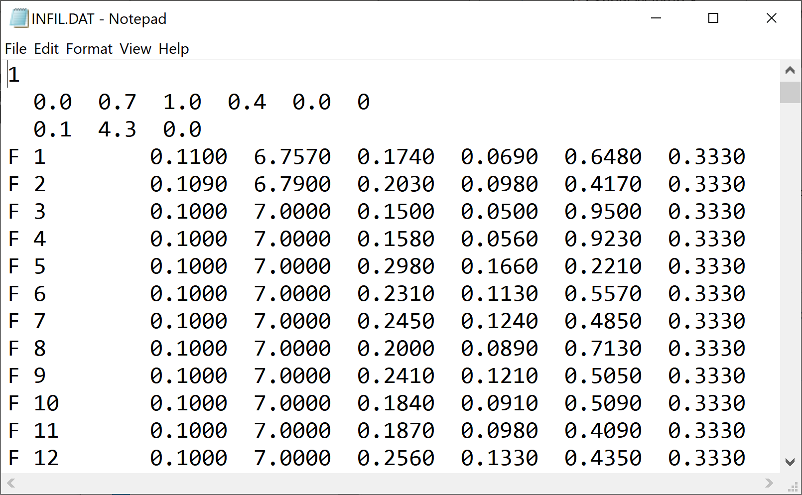
Figure 34. Example INFIL.DAT file.
VC
VC is the vegetative cover related to the topsoil horizon. Figure 35 shows the vegetative cover of the landuse layer.
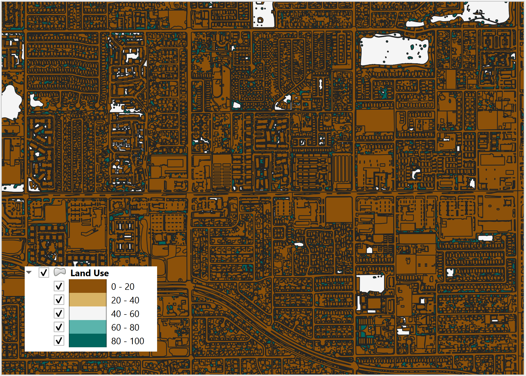
Figure 35. Landuse with Vegetative Cover.
It is used to adjust XKSAT (Eq. 2) as a function of the vegetation cover VC (Eq. 8) from the landuse table when XSAT < 0.4 in/hr. This requires a computation of the ratio of the hydraulic conductivity for the vegetative cover to the bare ground hydraulic conductivity equation (9):
Where:
Pk is the percentage of the area within the grid element corresponding to Ck and XKSATC for each grid element is written in the INFIL.DAT file.
IA
IA is the initial abstraction for each grid element. Figure 36 shows the initial abstraction for the landuse layer.
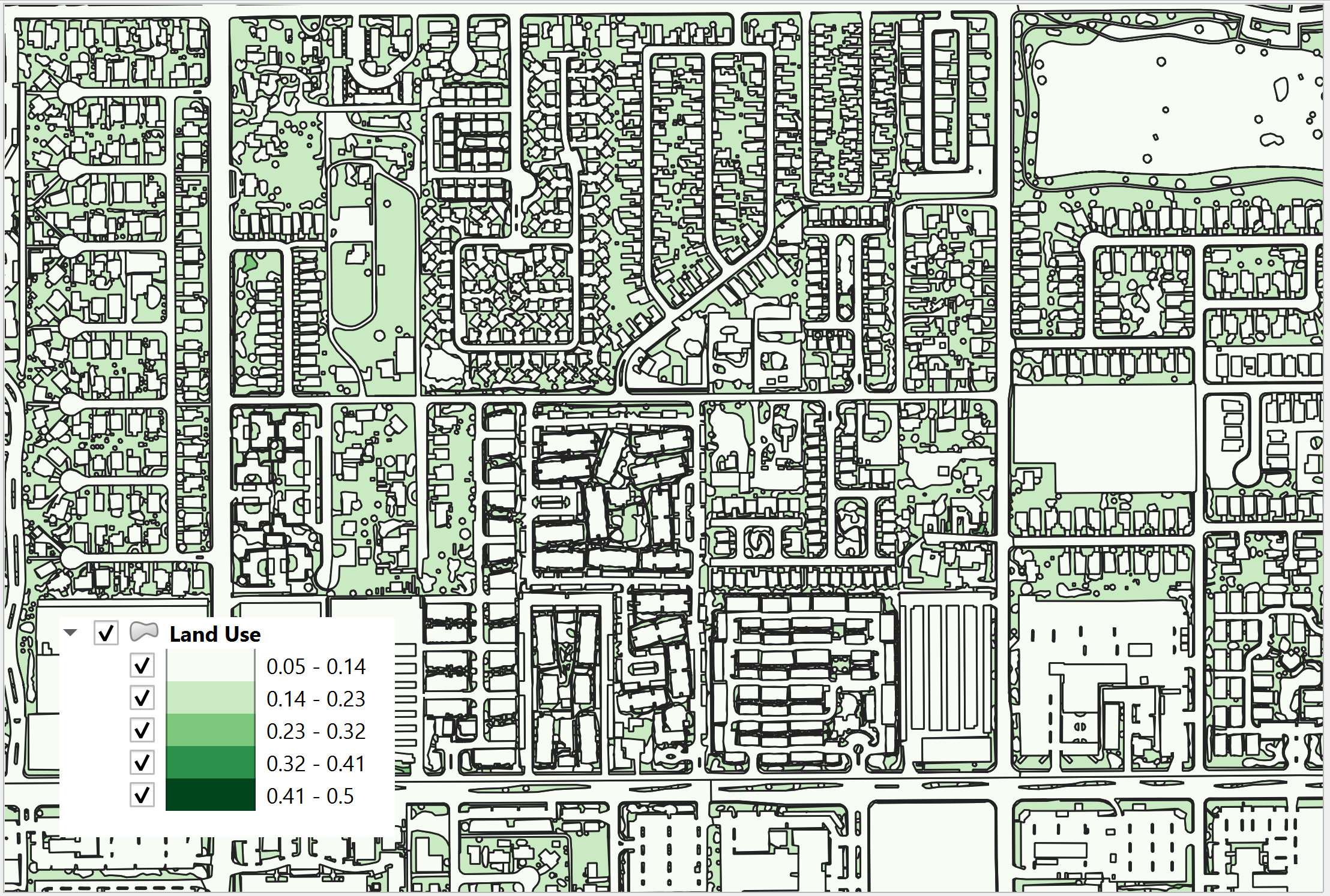
Figure 36. Landuse with Initial Abstraction.
The intersection between the landuse and grid element gives an area weighted average for the initial abstraction equation (10):
Where:
IAi is the initial abstraction in the subarea Ai intercepted by the element and is based on the 3rd column of the landuse table.
The intercepted subareas are computed using the landuse shape file and IABSTR is added to the INFIL.DAT file for each element.
Green and Ampt (FCDMC Method 2018)
The 2018 method for Green-Ampt uses a different calculator for PSIF and DTHETA. Figure 27 shows the Compute Green-Ampt dialog for the FCDMC Method 2018.
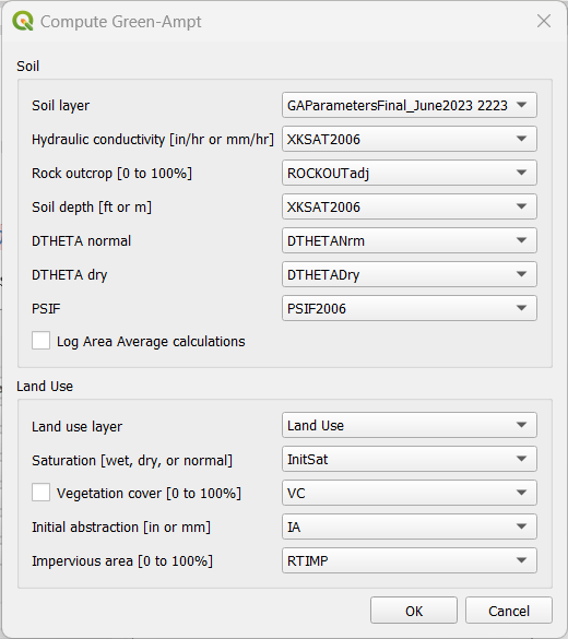
Figure 37. Green-Ampt dialog (FCDMC Method 2018).
For each grid element, compute wetting front capillary suction PSIF according to the following regressions as a function of XKSAT (Generated from Figure 4.3 of the Maricopa County Drainage Design Manual, 2018).
XKSAT (in/hr) |
PSIF (in) |
0.01 ≤ XKSAT ≤ 1.2 |
PSIF=EXP(0.9813-0.439*Ln(XKSAT)+0.0051(Ln(xk sat))2+0.0060(Ln(XKSAT))3) |
For each grid element, compute volumetric soil moisture deficiency (DTHETA) according to the following table. The specific table used for DTHETA depends on the saturation field of the soil table (6th column).
Moving Window Optimization
The moving window code is used to speed up the Green-Ampt infiltration calculator. This window is a geometric bounding box that samples a small set of grid elements at a time. The window size is 100 x 100 grid elements. The polygons are clipped to the window to eliminate duplicate calculations.
SCS Curve
There are two methods for assigning spatially variable SCS data. The Schematize method assigns data directly to the grid from polygons digitized to the Infiltration Areas layer. This is the most effective method.
The Calculator assigns the SCS curve number from a single external polygon. It can also calculate the Pima County method from a combined layer with soil, coverage density and impervious areas. Each method intersects the infiltration polygons to the grid and assigns an area weighted average to each grid element. The calculator method requires polygon layers with no geometric deficiencies and therefore is not as desirable as the Schematize method.
Horton
The Schematize Method assigns data directly to the grid from polygons digitized to the Infiltration Areas layer. The required data fields are:
fhorti – Initial infiltration rate
fhortf – Final infiltration rate
deca – Decay coefficient
The schematize method intersects the Horton polygons to the grid and assigns the variables using an area weighted average.
Channel Development Tools
The channel development tools use several methods and calculators for channel development. A channel is composed of three polyline layers for the banks and cross sections and a point layer for confluences. The channel layers are defined by intersecting the left banks to the grid at the nearest centroid to the left bank.
Left Bank Layers
The Left Bank User Layer defines the geographical position of the left bank. The Plugin uses this polyline layer to intersect and connect the left bank grid elements. The position of the left bank elements is dependent on the position of the polyline vertices. It is important to note that if left bank schematization does not have accurate bank coverage, more vertices may be required along the length of the polyline.
The Left Bank Schematic Layer is a polyline layer that represents the real position of the FLO-2D channel with a single vertex representing each channel element in a segment. Multiple polyline features are used to represent separate channel segments. Figure 38 shows a sample of the two separate layers.
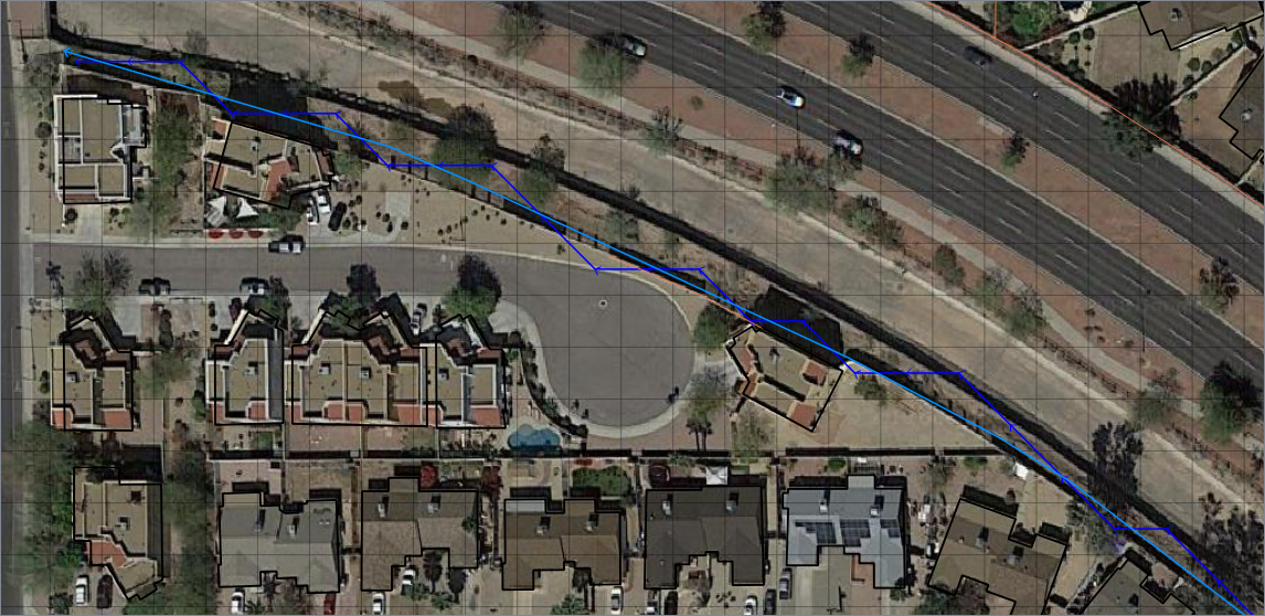
Figure 38. Left Bank Layers.
Cross Section Layers
The Channel Cross Section User Layer is used to define the channel geometry and the position of the right bank (Figure 39). The data requirement is station elevation data from the left top of bank to the right top of bank. The station elevation data is obtained from several sources including survey data or profile data from rasters or points. The data can also be defined for trapezoidal or rectangular channels. The last data source is a variable area equation such as: A = a*d^b. Where the area is defined by a coefficient, depth, and exponent.
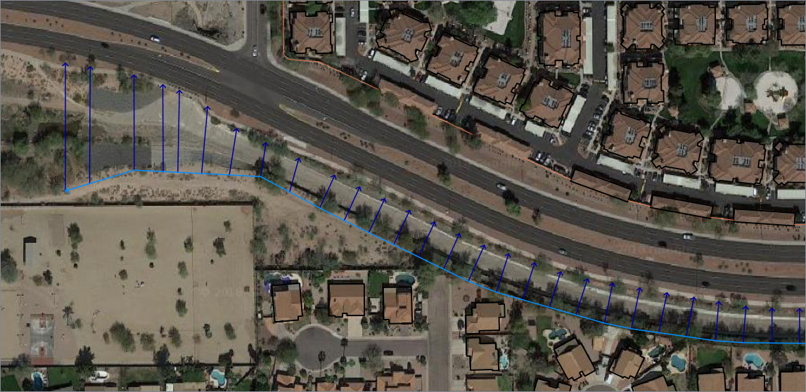
Figure 39. Cross Section User Layer.
Right Banks
The Standard schematization button will produce a right bank according to the position of the cross sections. It works somewhat similar to the left bank but will allow for more than one cross section to be assigned to a right bank.
Bank Elevation
The plugin uses two methods to define bank elevation. The first is to assign the bank elevation in the cross section data. This is the only method for N (Natural) channels as the bank elevation is assigned in the Station Elevation table. Assigning bank elevation is the preferred method for T (trapezoidal), R (rectangular), and V (variable area) channels. With this method, the left and right bank data is assigned to Left Bank Elevation and Right Bank Elevation fields in the Cross Section User Layer attributes.
The second bank elevation method is to leave the Left Bank Elevation and Right Bank Elevation variables NULL. This method only works with the T, R, and V channel types. The NULL variable assignment results in No Data being assigned to the Schematized Left Bank Layer. When no data is assigned, the Left Bank Elevation and Right Bank Elevation is not written to CHAN.DAT. The model uses the grid element elevation in lieu of the missing data.
Interpolation
The Plugin uses the same interpolator that the PROFILES program uses. It is an external App that is installed into the FLO-2D Pro subdirectory along with the FLO-2D software. The Plugin exports the CHAN.DAT, CHANBANK.DAT, and XSEC.DAT and executes the interpolation program. The data is reloaded into the Plugin Schematic Layers with the interpolation dialog box.
Import HEC-RAS
The Import HEC-RAS tool is used to import channel data from HEC-RAS geometry files. The RAS project must be georeferenced and in the same coordinate system as the GeoPackage. This system can import channel geometry, full cross sections, bank to bank cross sections, interpolated cross sections and levees.
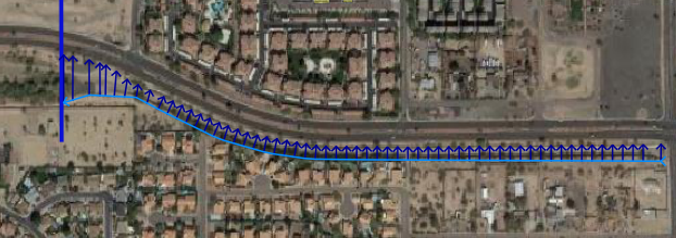
Figure 40. HEC-RAS Import.
Upon import, the HEC-RAS channels are saved to the User Layers (Figure 40). The data is saved to the left bank and cross section layers. It is important to note that the data imported to QGIS is read from the *.g0 file in linear order. The channels are imported as segment 1 being the first data set and segment 2 is next in order of the geometry file. If the channel data is in the wrong order, it should be corrected before being imported.
Cross sections are saved to the Cross Section layer in the order by which they were written to the geometry file. The cross section names are extracted from the river mile field (Figure 41).
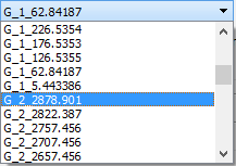
Figure 41. Channel Cross Sections.*
Storm Drain Development Tools
The FLO-2D surface water model has a dynamic exchange with the storm drain system. FLO-2D calculates the surface water depth at grid cells. Those cells that contain the storm drain inlets use the surface water depth and the inlet geometry, to compute the discharge inflow to the storm drain system. The storm drain engine then routes the flow in the pipe network and calculates potential return flow to the surface water system (Figure 42).
The Storm Drain Editor application and setup are well documented in the FLO-2D Plugin User Manual and a detailed tutorial is available online. This document will discuss data management and important algorithms in the calculators.
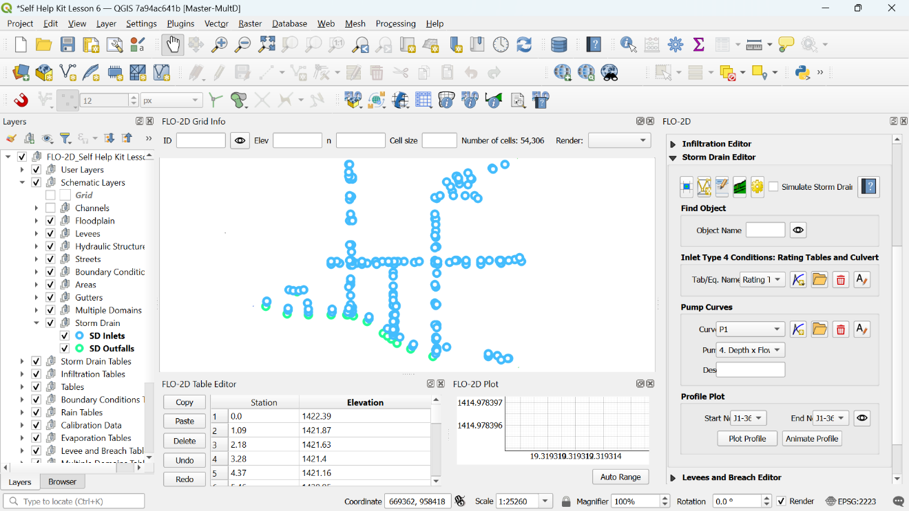
Figure 42. Storm Drain Layout in QGIS.
The Storm Drain data files (SWMM.INP and *.DAT files) can be developed from scratch in the FLO-2D Plugin Storm Drain Editor by assigning the data from shapefiles to the storm drain features. Figure 43 shows the Storm Drain dialog box.
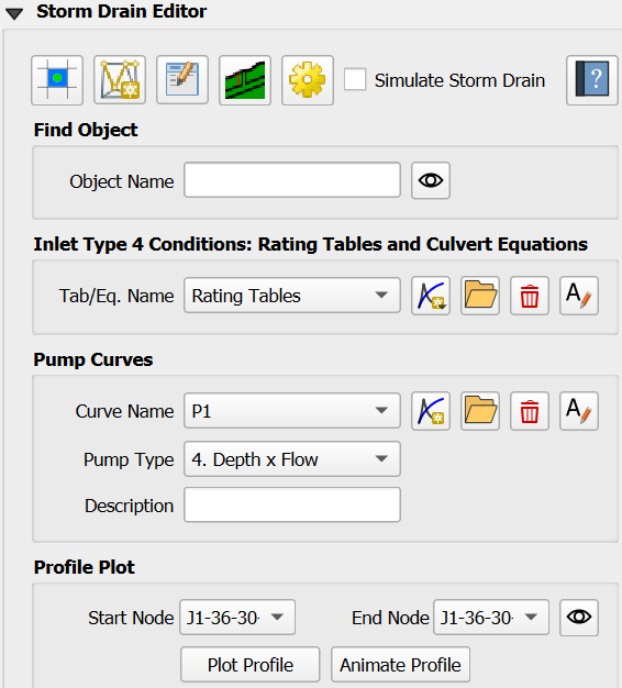
Figure 43. Storm Drain Dialog Box.
QGIS can be used to create the storm drain shapefiles for Inlets/Junctions, Outfalls and Conduits. These shapefiles contain all the required data to fill the Storm Drain data files (see FLO-2D Plugin User’s Manual and FLO-2D Storm Drain Manual for more information about the required data for each component). If the storm drain shapefiles exist, they can be imported into the QGIS project. If the storm drain shapefiles do not exist, they can be digitized into Storm Drain User Layers (Figure 44).
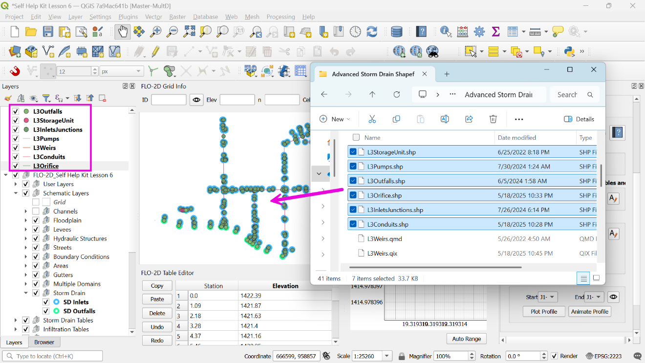
Figure 44. Storm Drain Shapefiles.
Storm Drain Components
The Storm Drain Configuration Tool (Figure 45), is the main processing tool for storm drain development. The algorithms copy features and attributes from shapefiles into the storm drain tables and layers. This organizes the data in a manner that is ideal for the swmm.inp, SWMMFLO.DAT, and SWMMOUTF.DAT data files.
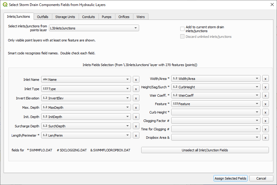
Figure 45. Select Components from Shapefile Layer: Inlet/Junctions.
The data layout and organization prevent array allocation errors between FLO-2D engine and the storm drain engine. The features are written in the correct order from between swmm.inp and SWMMFLO.DAT.
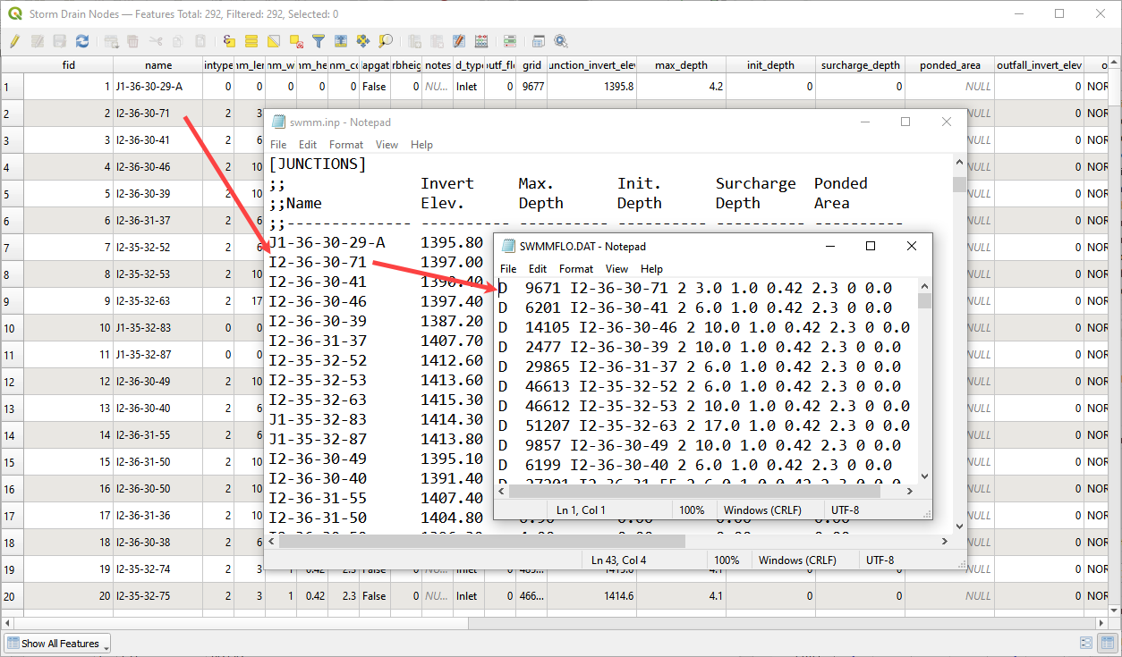
Figure 46. Data Organization Inlets.
The finished tables can be validated and edited with the node and link dialog boxes (Figure 47). These boxes highlight and pan/zoom to the current feature and allow extra data to be assigned. Changes to these dialog boxes automatically update the storm drain arrays.
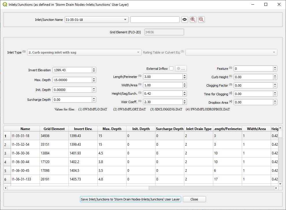
Figure 47. Review Attributes from Storm Drain Table.
Digitizing Storm Drain Features
Storm Drain features can be created in QGIS for the development of the INP file. Point layer shapefiles must be created for Inlets/Junctions and outfalls. Line Layer Shapefiles must be created for conduits. Once the shapefiles have been created, features from the shapefiles can be selected and assigned to the storm drain data.
The storm drain editor has an option to Select Components from Shapefile Layer in the Storm Drain Editor. The selected attributes will be assigned to the Inlets/Junctions, Outfalls and Conduits Components Tables in User Layers.
The data must be schematized using the schematize button in the Storm Drain Editor. Then the *.INP can be created by clicking Export SWMM.inp. Storm drain data files as: SWMMFLO.DAT file, SWMMOUTF.DAT File and SWMMFLORT.DAT file will be created when FLO-2D Data Files are exported in the QGIS Project. The Storm Drain component needs to be turned ON in the FLO-2D Control and Tolerance Variables.
Importing existing *.INP file
An existing *.INP file can be imported with the buttons in Figure 48 once the FLO-2D surface model has been already created. The Storm Drain Editor has an option to Import SWMM.inp that can be used to read an existing *.INP file. Storm drain systems created using other software can be imported if the format is compatible with EPA SWMM Version 5.
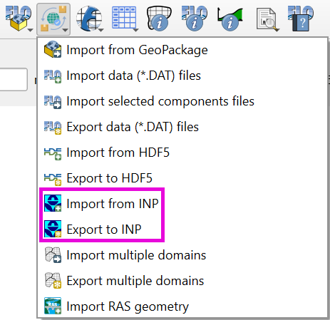
Figure 48. Import Export SWMM.INP Options.
The storm drain features will be read from the *.INP file and the Inlets/Junctions, Outfalls and Conduits tables in the components section in the Storm Drain Editor will be completed.
Auto assign nodes
The auto assign tool (Figure 49) scans the polyline data and finds the nodes at the upstream and downstream end. The node names fields from the Link tables are filled automatically.
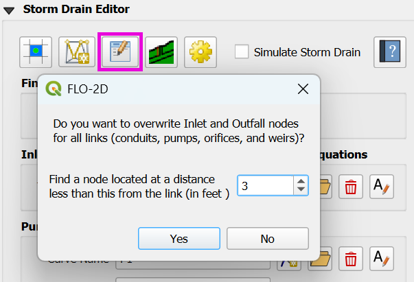
Figure 49. Auto Assign Tool.
The algorithm uses a loop to read the xy coordinate of each end of the polyline using the xat,yat vertex(1) and xat,yat vertex (-1). This calls the first and last vertex of each line. A small buffer is then applied to each of the points. If a node is within the buffer, it is assigned to the InNode or OutNode table for each of the Link features. It is important that the links are digitized in the correct flow direction. Arrows are used in the feature style to represent the flow direction. Figure 50 shows the nodes next to each end of the link and the flow direction is shown by the blue arrows.
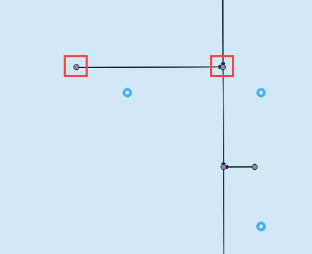
Figure 50. Link Node and Flow Direction.
Rating Tables and Pump Curves
The rating table and pump curve tools (Figure 51) can import or build tabular data for type 4 inlets and pumps. These tools are connected to the table and plotting windows shown in Figure 52. These tools facilitate data assignment by automatically finding node names or link names and assigning the data with the same name.
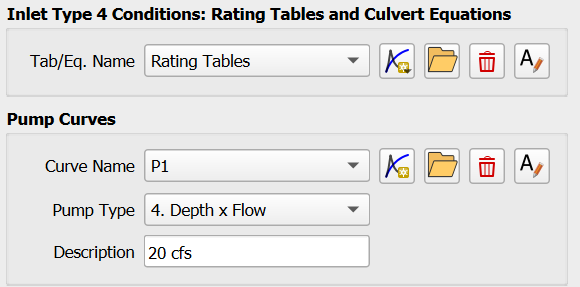
Figure 51. Rating Tables and Pump Curves.
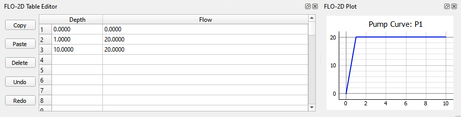
Figure 52. Table Editor and Plotting Window.
Hazus tools
The Hazus tool will generate a raster maximum depth file that can be used as an input for the FEMA Hazus program. The required layers include building shape files, grid cell elevations, grid cell depth and water surface elevations. The user must define ground elevation, water surface elevation and maximum flow depth for each building. An adjustment factor can be applied to calculate the finished floor elevation. Figure 53 shows the tool requirements.
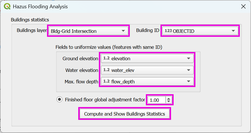
Figure 53. Hazus Tool.
The process to generate a Hazus raster is outlined in the User’s Manual. It requires the use of several general QGIS tools for importing, intersecting, calculating, and rasterizing data. The requirements and calculations are outlined below for each layer.
Building layer – This layer is used to define the building locations and set the building ID.
Depth and water surface data – FLO-2D results imported as text files.
Assign water surface and depth – This calculation process uses a simple Join feature to write the results into the Grid layer.
Intersect buildings layer – This QGIS process splits the building polygons into separate polygons for each grid element.
Homogenize the building intersection layer – This process joins the split buildings to the grid elevation, depth and water elevation data and calculates statistics for the building.
Join building statistics to building polygons – This QGIS process writes the stats back to the Buildings layer.
Rasterize – This QGIS process rasterizes building depth and water surface data for Hazus.
References
Library of Congress, 2017. Geopackage Encoding Standard (OGC), version 1.0, https://www.loc.gov/preservation/digital/formats/fdd/fdd000419.shtml
Python Software Foundation, 2018. The Python Tutorial, Python English 2.7.15 Documentation, https://docs.python.org/2.7/tutorial
Flood Control District of Maricopa County, 2018, Drainage Design Manual for Maricopa County, Arizona Hydrology.
Flood Control District of Maricopa County, 2023, Drainage Design Manual for Maricopa County, Arizona Hydrology.
Appendix A GeoPackage Structure
all_schem_bc
A table that stores the boundary condition cell data from the BC cells schematic layer.
Field Name |
Field Type |
Description |
fid |
INTEGER |
Unit fid is unique and not associated with the grid id. |
type |
TEXT |
Defines inlet or outlet. |
tab_bc_fid |
INTEGER |
Link to the hydrograph or stage timetable. |
grid_fid (DUM) |
INTEGER |
Grid element id of the cell. |
geom |
POLYGON |
Polygon of the cell. |
blocked_cells
This table lists the data stored in the ARF_WRF layer of the Schematic group. The ARF_WRF layer stores the data written to the ARF.DAT file.
Field Name |
Field Type |
Description |
fid |
INTEGER |
Unique id not related to the grid element. |
grid_fid (igd /ittawf) |
INTEGER |
Grid element id of the cell. |
area_fid |
INTEGER |
Id of the blocked areas layer in the User Layers group. |
arf |
REAL |
Area reduction factor. |
wrf1 |
REAL |
Width reduction factor north. |
wrf2 |
REAL |
Width reduction factor east. |
wrf3 |
REAL |
Width reduction factor south. |
wrf4 |
REAL |
Width reduction factor west. |
wrf5 |
REAL |
Width reduction factor northeast. |
wrf6 |
REAL |
Width reduction factor southeast. |
wrf7 |
REAL |
Width reduction factor southwest. |
wrf8 |
REAL |
Width reduction factor northwest. |
geom |
POINT |
A point layer but the style of the layer is set up to look like blocked cells with 8 direction blockage. |
breach
Individual breach data stored in the breach.dat file. This table works with import and export. It can be edited in the Breach layer of the Schematic Layers group.
Field Name |
Field Type |
Description |
fid |
INTEGER |
Unit fid is unique and not associated with the grid id. |
ibreachdir |
INTEGER |
Breach direction. |
zu |
REAL |
Upstream face slope. |
zd |
REAL |
Downstream face slope. |
zc |
REAL |
Upstream and downstream core slope. |
crestwidth |
REAL |
Crest width of the dam or levee. |
crestlength |
REAL |
Crest length of the dam or levee |
brbotwidmax |
REAL |
Maximum breach width at the bottom. |
brtopwidmax |
REAL |
Maximum breach width at the top of the breach. |
brbottomel |
REAL |
Minimum erosion elevation of the breach. |
weircoef |
REAL |
Weir coefficient. |
d50c |
REAL |
Mean sediment size core. |
porc |
REAL |
The porosity of the core material. |
uwc |
REAL |
Unit weight core. |
cnc |
REAL |
Manning’s n core. |
afrc |
REAL |
Angle of internal friction core. |
cohc |
REAL |
Cohesive strength core. |
unfcc |
REAL |
Sediment gradient core. |
d50s |
REAL |
Mean sediment size shell. |
pors |
REAL |
The porosity of the shell. |
uws |
REAL |
Unit weight shell. |
cns |
REAL |
Manning’s n shell. |
afrs |
REAL |
Angle of internal friction shell. |
cohs |
REAL |
Cohesive strength shell. |
unfcs |
REAL |
Sediment gradient shell. |
bratio |
REAL |
The ratio of initial breach width to depth. |
grasslength |
REAL |
Average grass length on downstream face. |
grasscond |
REAL |
The condition of the grass. Poor or Good. |
grassvmaxp |
REAL |
Maximum permissible velocity for the the grass-lined downstream face. |
sedconmax |
REAL |
Maximum sediment concentration. |
d50df |
REAL |
Mean sediment size of the downstream upper one foot face. |
unfcdf |
REAL |
Sediment gradient of the downstream upper one foot face. |
breachtime |
REAL |
Length of time between the initial breach condition and the start of the breach. |
geom |
POINT |
Breach layer is a point layer. |
breach_cells
Field Name |
Field Type |
Description |
fid |
INTEGER |
Unit fid is unique and not associated with the grid id or the breach id. |
breach_fid |
INTEGER |
Id that joins to the breach point layer. |
grid_fid (dum) |
INTEGER |
Grid element id of the cell. |
breach_fragility_curves
Field Name |
Field Type |
Description |
fid |
INTEGER |
Unit fid is unique and not associated with the grid id. |
fragchar |
TEXT |
Fragility character. |
prfail |
REAL |
Levee fragility failure probability. |
prdepth |
REAL |
The distance below levee crest paired with the failure probability. |
breach_global
Field Name |
Field Type |
Description |
fid |
INTEGER |
Unit fid is unique and not associated with the grid id. |
ibreachsedeqn |
INTEGER |
Breach sediment transport equation. |
gbratio |
REAL |
The ratio of the initial breach width to breach depth. |
gweircoef |
REAL |
Weir coefficient. |
gbreachtime |
REAL |
Time to start of erosion from when pipe elevation is reached. |
gzu |
REAL |
Upstream face slope. |
gzd |
REAL |
Downstream face slope. |
gzc |
REAL |
Upstream and downstream core slope. |
gcrestwidth |
REAL |
Crest width of the dam or levee. |
gcrestlength |
REAL |
Crest length of the dam or levee. |
gbrbotwidmax |
REAL |
Maximum breach width at the bottom. |
gbrtopwidmax |
REAL |
Maximum breach width at the top of the breach. |
gbrbottomel |
REAL |
Minimum erosion elevation of the breach. |
gd50c |
REAL |
D50 of the core material. |
gporc |
REAL |
The porosity of the core material. |
guwc |
REAL |
Unit weight core. |
gcnc |
REAL |
Manning’s n core. |
gafrc |
REAL |
Angle of internal friction core. |
gcohc |
REAL |
Cohesive strength core. |
gunfcc |
REAL |
Sediment gradient core. |
gd50s |
REAL |
Mean sediment size shell. |
gpors |
REAL |
The porosity of the shell. |
guws |
REAL |
Unit weight shell. |
gcns |
REAL |
Manning’s n shell. |
gafrs |
REAL |
Angle of internal friction shell. |
gcohs |
REAL |
Cohesive strength shell. |
gunfcs |
REAL |
Sediment gradient shell. |
ggrasslength |
REAL |
Average grass length on downstream face. |
ggrasscond |
REAL |
Condition of grass. Poor or Good. |
ggrassvmaxp |
REAL |
Maximum permissible velocity for grass lined downstream face. |
gsedconmax |
REAL |
Maximum sediment concentration. |
d50df |
REAL |
Mean sediment size of the downstream upper one foot face. |
gunfcdf |
REAL |
Sediment gradient of the downstream upper one foot face. |
bridge_variables
Field Name |
Field Type |
Description |
fid |
INTEGER |
Unit fid is unique and not associated with the grid id. |
struct_fid |
INTEGER |
structure fid for which the data are defined “IBTYPE” INTEGER |
IBTYPE |
INTEGER |
Type of bridge configuration (see Appendix figures) “COEFF” |
COEFF |
REAL |
Overall bridge discharge coefficient assigned or computed (default = 0.) “C_PRIME_USER” |
C_PRIME_USER |
REAL |
Baseline bridge discharge coefficient to be adjusted with detail coefficients “KF_COEF” |
KF_COEF |
REAL |
Froude number coefficient assigned or computed (= 0.) “KWW_COEF” |
KWW_COEF |
REAL |
Wingwall coefficient assigned or computed (= 0.) “KPHI_COEF” |
KPHI_COEF |
REAL |
Flow angle with bridge coefficient assigned or computed (= 0.) “KY_COEF” |
KY_COEF |
REAL |
Coefficient associated with sloping embankments and vertical abutments (= 0.) “KX_COEF” |
KX_COEF |
REAL |
Coefficient associated with sloping abutments assigned or computed (= 0.) “KJ_COEF” |
KJ_COEF |
REAL |
Coefficient associated with pier and piles assigned or computer (= 0.) “BOPENING” |
BOPENING |
REAL |
Bridge opening width (ft or m). See Figure 7. “BLENGTH” |
BLENGTH |
REAL |
Bridge length from upstream edge to downstream abutment (ft or m) “BN_VALUE” |
BN_VALUE |
REAL |
Bridge reach n-value (typical channel n-value for the bridge cross section) “UPLENGTH12” |
UPLENGTH12 |
REAL |
Distance to upstream cross section unaffected by bridge backwater (ft or m) “LOWCHORD” |
LOWCHORD |
REAL |
Average elevation of the low chord (ft or m). “DECKHT” |
DECKHT |
REAL |
Average elevation of the top of the deck railing for overtop flow (ft or m) “DECKLENGTH” |
DECKLENGTH |
REAL |
Deck weir length (ft or m). “PIERWIDTH” |
PIERWIDTH |
REAL |
Combined pier or pile cross section width (flow blockage width in ft or m) “SLUICECOEFADJ” |
SLUICECOEFADJ |
REAL |
Adjustment factor to raise or lower the sluice gate coefficient which is 0.33 for Yu/Z = 1.0 “ORIFICECOEFADJ” |
ORIFICECOEFADJ |
REAL |
Adjustment factor to raise or lower the orifice flow coefficient which is 0.80 for
|
COEFFWEIRB |
REAL |
Weir coefficient for flow over the bridge deck. For metric: COEFFWIERB x 0.552 WINGWALL_ANGLE |
WINGWALL_ANGLE |
REAL |
Angle the wingwall makes with the abutment perpendicular to the flow PHI_ANGLE |
PHI_ANGLE |
REAL |
Angle the flow makes with the bridge alignment perpendicular to the flow LBTOEABUT |
LBTOEABUT |
REAL |
Toe elevation of the left abutment (ft or m) |
RBTOEABUT |
REAL |
Toe elevation of the right abutment (ft or m) |
bridge_xs
Table for bridge upstream and downstream cross section identification.
Field Name |
Field Type |
Description |
fid |
INTEGER |
Unit fid is unique and not associated with the grid id. |
struct_fid |
INTEGER |
Unique id for the hydraulic structure that the bridge cross section matches. |
xup |
REAL |
Station in ft or m. |
yup |
REAL |
Elevation in ft or m. |
yb |
REAL |
Distance from bridge to up cross section. |
buildings_areas
Field Name |
Field Type |
Description |
fid |
INTEGER |
Unit fid is unique and not associated with the grid id. |
adjustment_factor |
INTEGER |
|
geom |
POLYGON |
A layer with polygon geometry. |
building_stats
Field Name |
Field Type |
Description |
fid |
INTEGER |
Unit fid is unique and not associated with the grid id. |
building_id |
INTEGER
|
Unique building id
matches the features
in building areas.
|
grnd_elev_avg |
REAL |
Average ground elevation intersected to the building footprint. (ft or m) |
grnd_elev_min |
REAL |
Min ground elevation intersected to the building footprint. (ft or m) |
grnd_elev_max |
REAL
|
Max ground elevation
intersected to the
building footprint.
(ft or m)
|
floor_avg |
REAL |
Average floor elevation of grid elements intersected with building footprints. (ft or m) |
floor_min |
REAL |
Min floor elevation of grid elements intersected with building footprints. (ft or m) |
floor_max |
REAL |
Max floor elevation of grid elements intersected with building footprints. (ft or m) |
water_elev_avg |
REAL |
Average water elevation of grid elements intersected with building footprints. (ft or m) |
water_elev_min |
REAL |
Min water elevation of grid elements intersected with building footprints. (ft or m) |
water_elev_max |
REAL |
Max water elevation of grid elements intersected with building footprints. (ft or m) |
depth_avg |
REAL |
Average water depth of grid elements intersected with building footprints. (ft or m) |
depth_min |
REAL |
Min water depth of grid elements intersected with building footprints. (ft or m) |
depth_max |
REAL |
Max water depth of grid elements intersected with building footprints. (ft or m) |
geom |
POLYGON |
Polygon geometry. |
chan
Table for the Channel Segments (left banks) layer in the Schematic Layers group. This layer stores the data that is written to the chanbank.dat for each channel segment control line. It also sets the rank of each channel in the chan.dat file so that the channel matches the position of the cross-sections. Channel are written in order from rank = 1 to n number of segments.
Field Name |
Field Type |
Description |
fid |
INTEGER |
Unit fid is unique and not associated with the grid id. |
name |
TEXT |
Segment name. |
depinitial |
REAL |
Initial depth. |
froudc |
REAL |
Limiting Froude. |
roughadj |
REAL |
Manning’s n adjustment factor. |
isedn |
INTEGER |
Channel sediment switch. |
notes |
TEXT |
Notes. |
user_lbank_fid |
INTEGER |
Left bank id links channel segment to a left bank line. |
rank |
INTEGER |
Rank order in the chan.dat file. |
geom |
LINESTRING |
Polyline. |
chan_confluences
Table of data associated with the Channel Confluences layer in the Schematic Layers group. This table identifies the connecting channel cells and identifies if a confluence cell is a tributary or main channel element.
Field Name |
Field Type |
Description |
fid |
INTEGER |
Unit fid is unique and not associated with the grid id, confluence or the channel id. |
conf_fid |
INTEGER |
Id of confluence pair. |
type |
TEXT |
Tributary or Main. |
chan_elem_fid(iconflo1,iconflo2) |
INTEGER |
Left or right bank id of the channel cell being connected. |
notes |
TEXT |
Notes. |
geom |
POINT |
Point associated with the channel cell for a tributary or main element. |
chan_elems
Table associated with all Channel Cross Sections layer in the Schematic Layers group. This table uses several id fields to link the cross sections to the correct channel segment, left bank element, right bank element and station or geometry data.
Field Name |
Field Type |
Description |
id |
INTEGER |
Unit fid is unique and not associated with the grid id, seg id, xsec id. |
Fid (leftbank) |
INTEGER |
Left bank grid element id. |
seg_fid |
INTEGER |
Segment id from chan layer. |
nr_in_seg |
INTEGER |
Rank of channel element in segment. |
Rbankgrid (rightbank) |
INTEGER |
Right bank grid element id. |
fcn |
REAL |
Manning’s n number of channel cross section. |
xlen |
REAL |
Length of channel element. |
type |
TEXT |
Geometry type. R, T, N, V |
notes |
TEXT |
Notes. |
user_xs_fid(nxsecnum) |
INTEGER |
Cross section id links each polyline to the cross section data table. |
interpolated |
INTEGER |
Interpolated cross section. 0 non interpolated 1 interpolated. |
max_water_elev |
REAL |
Maximum water elevation imported from hychan.out |
peak_discharge |
REAL |
Peak q imported from hychan.out |
geom |
LINESTRING |
Polyline. |
chan_elems_interp
This table is used for a calculation scheme that calculates the distance between channel cross sections for the purpose of interpolation. The table is referenced in two python files. They are Schematic_tools.py and flo2dobjects.py.
Field Name |
Field Type |
Description |
id |
INTEGER |
Id of the interpolated cross section. |
fid |
INTEGER |
Unit fid is unique and not associated with the grid id. |
seg_fid |
INTEGER |
Channel segment id. |
up_fid |
INTEGER |
Id of the upstream cross section. |
lo_fid |
INTEGER |
Id of the downstream cross section. |
up_lo_dist_left |
REAL |
Distance from upstream cross section to current cross section. |
up_lo_dist_right |
REAL |
Distance from current cross section to downstream cross section. |
up_dist_left |
REAL |
Distance from left bank to center. |
up_dist_right |
REAL |
Distance from right bank to center. |
chan_n
Table that stores the data that links natural cross-sections to left bank elements.
Field Name |
Field Type |
Description |
fid |
INTEGER |
Unit fid is unique and not associated with the grid id. |
elem_fid (ichangrid) |
INTEGER |
Left bank grid element id of the cell. |
nxsecnum |
INTEGER |
Natural cross section number. |
xsecname |
TEXT |
Cross section name. |
chan_r
The table that stores the cross-section data for rectangular cross sections and links them to left bank elements.
Field Name |
Field Type |
Description |
fid |
INTEGER |
Unit fid is unique and not associated with the grid id. |
elem_fid (ichangrid) |
INTEGER |
Left bank grid element id of the cell. |
bankell |
REAL |
Left bank elevation. |
bankelr |
REAL |
Right bank elevation. |
fcw |
REAL |
Channel width. |
fcd |
REAL |
Channel depth. |
chan_t
The table that stores the cross-section data for trapezoidal cross sections and links them to left bank elements.
Field Name |
Field Type |
Description |
fid |
INTEGER |
Unit fid is unique and not associated with the grid id. |
elem_fid (ichangrid) |
INTEGER |
Left bank grid element id of the cell. |
bankell |
REAL |
Left bank elevation. |
bankelr |
REAL |
Right bank elevation. |
fcw |
REAL |
Channel width. |
fcd |
REAL |
Channel depth. |
zl |
REAL |
Left bank slope. |
zr |
REAL |
Right bank slope. |
chan_v
The table that stores the cross-section data for variable area regression cross sections and links them to left bank elements.
Field Name |
Field Type |
Description |
fid |
INTEGER |
Unit fid is unique and not associated with the grid id. |
elem_fid (ichangrid) |
INTEGER |
Left bank grid element id of the cell. |
bankell |
REAL |
Left bank elevation. |
bankelr |
REAL |
Right bank elevation. |
fcd |
REAL |
Channel depth. |
a1 |
REAL |
Coefficient area a1. |
a2 |
REAL |
Exponent area a2. |
b1 |
REAL |
Coefficient wetted perimeter b1. |
b2 |
REAL |
Exponent wetted perimeter b2. |
c1 |
REAL |
Coefficient top width c1. |
c2 |
REAL |
Exponent top width c2. |
excdep |
REAL |
Second equation starts when channel reaches this depth. |
a11 |
REAL |
Coefficient area (depth 2) a11. |
a22 |
REAL |
Exponent area (depth 2) a22. |
b11 |
REAL |
Coefficient wetted perimeter (depth 2) b11. |
b22 |
REAL |
Exponent wetted perimeter (depth 2) b22. |
c11 |
REAL |
Coefficient top width (depth 2) c11. |
c22 |
REAL |
Exponent top width (depth 2) c22. |
chan_wsel
Table connecting the initial conditions to specific channel segments.
Field Name |
Field Type |
Description |
fid |
INTEGER |
Unit fid is unique and not associated with the grid id. |
seg_fid |
INTEGER |
Channel segment id. |
istart |
INTEGER |
Channel element number that starts the water surface elevation. |
wselstart |
REAL |
Elevation at the start. |
iend |
INTEGER |
Channel element number that ends the water surface elevation. |
wselend |
REAL |
Elevation at the end. |
cont
Field Name |
Field Type |
Description |
fid |
INTEGER |
Unit fid is unique and not associated with the grid id. |
name |
TEXT |
Name field. |
value |
TEXT |
Value field. |
note |
TEXT |
Notes. |
culvert_equations
The table that stores the data for the generalized culvert equations and linked to the Structures Layer.
Field Name |
Field Type |
Description |
fid |
INTEGER |
Unit fid is unique and not associated with the grid id. |
struct_fid |
INTEGER |
Hydraulic structure id from structures layer. |
typec |
INTEGER |
Culvert type box or circular. |
typeen |
INTEGER |
Entrance type. |
culvertn |
REAL |
Manning’s n value. |
ke |
REAL |
Contraction value. |
cubase |
REAL |
Culvert width. |
multibarrels |
INTEGER |
Multiple barrels. |
evapor
The table that stores the start time and date for the Evaporation group.
Field Name |
Field Type |
Description |
fid |
INTEGER |
Unit fid is unique and not associated with the grid id. |
ievapmonth |
INTEGER |
Starting month of simulation. 1-12 |
iday |
INTEGER |
Starting day of the week. 1-7 |
clocktime |
REAL |
Starting clock time hours. |
evapor_hourly
Temporal evaporation information related to the evaporation of a specific calendar.
Field Name |
Field Type |
Description |
fid |
INTEGER |
Unit fid is unique and not associated with the grid id. |
month |
TEXT |
Name of evaporation month. |
hour |
INTEGER |
Evaporation hour. |
hourly_evap |
REAL |
Evaporation rate. |
evapor_monthly
Field Name |
Field Type |
Description |
fid |
INTEGER |
Unit fid is unique and not associated with the grid id. |
month |
TEXT |
Month. |
monthly_evap |
REAL |
Monthly evaporation rate. |
external_layers
Field Name |
Field Type |
Description |
fid |
INTEGER |
Unit fid is unique and not associated with the grid id. |
name |
TEXT |
Layer name. |
type |
TEXT |
A field to determine if and external layer is a user layer meaning part of the GeoPackage or external layer that is not part of the GeoPackage. |
fpfroude
The table that lists the data for the Froude Areas layer in the User Layers group. This polygon layers stores the spatially variable limiting Froude data.
Field Name |
Field Type |
Description |
fid |
INTEGER |
Unit fid is unique and not associated with the grid id. |
froudefp |
REAL |
Limting Froude. |
geom |
POLYGON |
Polygon features that outline the limiting Froude areas. |
fpfroude_cells
A table of cells that are written to the froudefp.dat when the project is exported.
Field Name |
Field Type |
Description |
fid |
INTEGER |
Unit fid is unique and not associated with the grid id. |
area_fid |
INTEGER |
This ID is joined to the fpfroude table from the User Layers. |
grid_fid (idum) |
INTEGER |
Grid element id of the cell. |
fpxsec
Table for the Floodplain Cross Sections layer in the Schematic Layers group. Stores the order of cross sections listed in fpxsec.dat.
Field Name |
Field Type |
Description |
fid |
INTEGER |
Unit fid is unique and not associated with the grid id. |
iflo |
INTEGER |
Flow direction 1 – 8. |
nnxsec |
INTEGER |
Cross section number. |
geom |
LINESTRING |
Polyline representing the exact location of the floodplain cross section. |
fpxsec_cells
Table for the Floodplain Cross Sections Cells. Lists the cells in each floodplain cross section as written to fpxsec.dat.
Field Name |
Field Type |
Description |
fid |
INTEGER |
Unit fid is unique and not associated with the grid id. |
fpxsec_fid |
INTEGER |
Floodplain cross-section id. |
grid_fid (nodx) |
INTEGER |
Grid element id of the cell. |
geom |
POINT |
Point geometry to identify the cells in each floodplain cross section. |
gpkg_contents
OGC GeoPackage Encoding Standard Table (Open Geospatial Consortium, 2017).
Field Name |
Field Type |
Description |
table_name |
TEXT |
Name of the table in the Geopackage. |
data_type |
TEXT |
Data types include aspatial for table data, features for vector data and 2d-gridded-coverage for raster data. |
identifier |
TEXT |
Name of external data. |
description |
TEXT |
No data available. |
last_change |
DATETIME |
Last data change of table or layer. If it’s external data, the date is added date and if its GeoPackage data, the date is last saved. |
min_x |
DOUBLE |
Assigned when features are added. Left x coordinate. |
min_y |
DOUBLE |
Assigned when features are added. Bottom y coordinate. |
max_x |
DOUBLE |
Assigned when features are added. Right x coordinate. |
max_y |
DOUBLE |
Assigned when features are added. Top y coordinate. |
srs_id |
INTEGER |
EPSG code. |
gpkg_data_column_constraints
OGC GeoPackage Encoding Standard Table (Open Geospatial Consortium, 2017).
Field Name |
Field Type |
Description |
constraint_name |
TEXT |
Unique name for the constraint. |
constraint_type |
TEXT |
Type of constraint: ‘range’, ‘enum’, or ‘glob’. |
value |
TEXT |
The allowed value or pattern. |
min |
NUMERIC |
Minimum value for ‘range’ constraint. |
minIsInclusive |
BOOLEAN |
1 if the minimum is inclusive; 0 if exclusive. |
max |
NUMERIC |
Maximum value for ‘range’ constraint. |
maxIsInclusive |
BOOLEAN |
1 if the maximum is inclusive; 0 if exclusive. |
description |
TEXT |
A human-readable description of the constraint. |
gpkg_data_columns
OGC GeoPackage Encoding Standard Table (Open Geospatial Consortium, 2017).
Field Name |
Field Type |
Description |
table_name |
TEXT |
Name of the user-defined table containing the column. |
column_name |
TEXT |
Name of the column within the user-defined table. |
name |
TEXT |
A human-readable name for the column. |
title |
TEXT |
A short descriptive title for display purposes. |
description |
TEXT |
A longer description explaining the purpose or contents of the column. |
mime_type |
TEXT |
MIME type of the data in the column (e.g., ‘text/plain’, ‘image/png’). |
constraint_name |
TEXT |
Optional name of the constraint from gpkg_data_column_constraints. |
gpkg_extensions
OGC GeoPackage Encoding Standard Table (Open Geospatial Consortium, 2017).
Field Name |
Field Type |
Description |
table_name |
TEXT |
Name of the table to which the extension applies, or NULL if it is global. |
column_name |
TEXT |
Name of the column to which the extension applies, or NULL if not specific. |
extension_name |
TEXT |
Unique name of the extension (e.g., ‘gpkg_rtree_index’). |
definition |
TEXT |
Reference URL or definition of the extension. |
scope |
TEXT |
Indicates how the extension is used: ‘read-write’, ‘write-only’, or ‘read-only’. |
gpkg_geometry_columns
OGC GeoPackage Encoding Standard Table (Open Geospatial Consortium, 2017).
Field Name |
Field Type |
Description |
table_name |
TEXT |
Name of the user-defined table containing the geometry column. |
column_name |
TEXT |
Name of the geometry column in the table. |
geometry_type_name |
TEXT |
Type of geometry stored (e.g., ‘POINT’, ‘LINESTRING’, ‘POLYGON’). |
srs_id |
INTEGER |
Spatial Reference System Identifier (must match an entry in gpkg_spatial_ref_sys). |
z |
TINYINT |
Indicates presence of Z values: 0 = none, 1 = mandatory, 2 = optional. |
m |
TINYINT |
Indicates presence of M values: 0 = none, 1 = mandatory, 2 = optional. |
gpkg_metadata
OGC GeoPackage Encoding Standard Table (Open Geospatial Consortium, 2017).
Field Name |
Field Type |
Description |
id |
INTEGER |
Unique identifier for the gpkg_metadata. |
md_scope |
TEXT |
Scope of the metadata (e.g., ‘dataset’, ‘featureType’, ‘tile’). |
md_standard_uri |
TEXT |
URI identifying the metadata standard or profile (e.g., ISO 19115, FGDC). |
mime_type |
TEXT |
MIME type of the metadata content (e.g., ‘text/xml’, ‘text/html’). |
metadata |
TEXT |
The actual metadata content stored as a text string. |
gpkg_metadata_reference
OGC GeoPackage Encoding Standard Table (Open Geospatial Consortium, 2017).
Field Name |
Field Type |
Description |
reference_scope |
TEXT |
Scope of the reference: ‘geopackage’, ‘table’, ‘column’, ‘row’, ‘row/col’. |
table_name |
TEXT |
Name of the table the metadata refers to (nullable if reference_scope = ‘geopackage’). |
column_name |
TEXT |
Name of the column the metadata refers to (nullable unless reference_scope includes ‘column’). |
row_id_value |
INTEGER |
Row ID if the metadata applies to a specific row (nullable unless scope includes ‘row’). |
timestamp |
DATETIME |
ISO 8601-formatted timestamp when the metadata reference was created. |
md_file_id |
INTEGER |
Foreign key to the gpkg_metadata.id that this reference links to. |
md_parent_id |
INTEGER |
Optional foreign key to a parent metadata record for hierarchical relationships. |
gpkg_spatial_ref_sys
OGC GeoPackage Encoding Standard Table (Open Geospatial Consortium, 2017).
Field Name |
Field Type |
Description |
srs_name |
TEXT |
Human-readable name of the spatial reference system. |
srs_id |
INTEGER |
Unique identifier for the spatial reference system. |
organization |
TEXT |
Name of the organization defining the coordinate system (e.g., ‘EPSG’). |
organization_coordsys_id |
INTEGER |
The numeric ID of the coordinate system in the organization’s registry (e.g., EPSG code). |
definition |
TEXT |
Well-Known Text (WKT) definition of the spatial reference system. |
description |
TEXT |
Optional description of the coordinate reference system. |
gpkg_tile_matrix
OGC GeoPackage Encoding Standard Table (Open Geospatial Consortium, 2017).
Field Name |
Field Type |
Description |
table_name |
TEXT |
Name of the tile pyramid user data table this matrix belongs to. |
zoom_level |
INTEGER |
Zoom level of the tile matrix (0 = least detailed, higher = more detail). |
matrix_width |
INTEGER |
Number of tiles in the width (columns) of the matrix at this zoom level. |
matrix_height |
INTEGER |
Number of tiles in the height (rows) of the matrix at this zoom level. |
tile_width |
INTEGER |
Width of each tile in pixels. |
tile_height |
INTEGER |
Height of each tile in pixels. |
pixel_x_size |
DOUBLE |
Size of a pixel in the x direction (map units per pixel). |
pixel_y_size |
DOUBLE |
Size of a pixel in the y direction (map units per pixel). |
gpkg_tile_matrix_set
OGC GeoPackage Encoding Standard Table (Open Geospatial Consortium, 2017).
Field Name |
Field Type |
Description |
table_name |
TEXT |
Name of the tile user data table that this tile matrix set belongs to. |
srs_id |
INTEGER |
Spatial reference system ID from the gpkg_spatial_ref_sys table. |
min_x |
DOUBLE |
Minimum X coordinate (longitude or easting) of the tile matrix set extent. |
min_y |
DOUBLE |
Minimum Y coordinate (latitude or northing) of the tile matrix set extent. |
max_x |
DOUBLE |
Maximum X coordinate of the tile matrix set extent. |
max_y |
DOUBLE |
Maximum Y coordinate of the tile matrix set extent. |
grid
Table for the Grid layer in the Schematic Layers group. Used to store the grid element number, n_value and elevation. Data saved to topo.dat and mannings.dat.
Field Name |
Field Type |
Description |
fid (dum) |
INTEGER |
Grid element id of the cell. |
col |
INTEGER |
Row id. |
row |
INTEGER |
Column id. |
n_value (fpnvalue) |
REAL |
Manning’s n-value for each cell. |
elevation (elev) |
REAL |
Elevation for each cell. |
water_elevation |
REAL |
Imported water surface elevation. |
flow_depth |
REAL |
Imported flow depth. |
geom |
POLYGON |
Polygons define the grid system based on the cells size. |
gutter_areas
The Gutter_Areas layer is used to define the spatial position of gutters. It also contains local variables used in gutter cells.
Field Name |
Field Type |
Description |
fid |
INTEGER |
Unit fid is unique and not associated with the grid id. |
width (widstr) |
REAL |
Individual cell street width. |
height (curbht) |
REAL |
Individual cell curb height. |
n_value (xnstr) |
REAL |
Individual cell street n-value. |
direction (icurbdir) |
INTEGER |
Curb direction. |
geom |
POLYGON |
Polygons define the grid system based on the cells size. |
gutter_cells
The gutter cells calculated from the gutter_areas. These are written to the GUTTER.DAT file when the project is exported.
Field Name |
Field Type |
Description |
fid |
INTEGER |
Unit fid is unique and not associated with the grid id. |
area_fid |
INTEGER |
The fid that is associated with the gutter area polygons. |
line_fid |
INTEGER |
The fid that is associated with the gutter line polylines. |
grid_fid |
INTEGER |
Grid element id of the cell. |
gutter_globals
The gutter_globals layer is a table that stores the global gutter variables. It is exported to GUTTER.DAT when the project is exported.
Field Name |
Field Type |
Description |
fid |
INTEGER |
Unit fid is unique and not associated with the grid id. |
height (strwidth) |
REAL |
Global curb height. |
width (curbheight) |
REAL |
Global street width. |
n_value(street_n-value) |
REAL |
Global gutter n-value |
gutter_lines
The gutter_lines layer is a polyline layer that stores the gutter lines. It is exported to intersected to the gutter_cells table when the gutter calculator is applied.
Field Name |
Field Type |
Description |
fid |
INTEGER |
Unit fid is unique and not associated with the grid id. |
width (strwidth) |
REAL |
Gutter street width. |
height (curbheight) |
REAL |
Gutter height. |
n_value (guttern-value) |
REAL |
Gutter n-value |
direction |
||
geom |
POLYLINE |
Polyline geometry type. |
infil
Table of global infiltration parameters for Green-Ampt, SCS, and Horton.
Field Name |
Field Type |
Description |
fid |
INTEGER |
Unit fid is unique and not associated with the grid id. |
infmethod |
INTEGER |
Grid element id of the cell. |
abstr |
REAL |
Initial abstraction global. (in or mm) |
sati |
REAL |
Initial saturation global. (decimal percentage) |
satf |
REAL |
Final saturation global. (decimal percentage usually 1) |
poros |
REAL |
Porosity global. (in^3 or mm^3) |
soild |
REAL |
Soil depth global. The spatially variable soil depth will not be used unless this value is greater than zero (ft or m). |
infchan |
INTEGER |
Infiltration channel switch. |
hydcall |
REAL |
Hydraulic conductivity global. (in/hr or mm/hr) |
soilall |
REAL |
Capillary soil suction global. (in or mm) |
hydcadj |
REAL |
Hydraulic conductivity adjustment. This variable will adjust spatially hydraulic conductivity per the conditions in the data Input Manual (no units). |
hydcxx |
REAL |
Channel hydraulic conductivity global. (in/hr or mm/hr) |
scsnall |
REAL |
SCS curve number global. Do not use a value greater than 99. |
abstr1 |
REAL |
SCS initial abstraction global. (in or mm) |
fhortoni |
REAL |
Horton initial infiltration rate global. (in/hr only) |
fhortonf |
REAL |
Horton final infiltration rate global. (in/hr only) |
decaya |
REAL |
Horton decay coefficient global. (no units) |
infil_cells_green
Tables that stores green-ampt infiltration parameters for specific grid elements.
Field Name |
Field Type |
Description |
fid |
INTEGER |
Unit fid is unique and not associated with the grid id. |
grid_fid (infgrid) |
INTEGER |
Grid element id of the cell. |
hydc |
REAL |
Hydraulic conductivity for a specific grid element. (in/hr or mm/hr) |
soils |
REAL |
Capillary soil suction for a specific grid element. (in or mm) |
dtheta |
REAL |
Soil volumetric void ratio for a specific grid element. (unitless volume ratio) |
abstrinf |
REAL |
Initial abstraction for a specific grid element. (in or mm) |
soil_depth |
REAL |
Limiting soil infiltration depth for a specific grid element. (ft or m) |
infil_cells_horton
Table that stores the Horton infiltration parameters for specific grid elements.
Field Name |
Field Type |
Description |
fid |
INTEGER |
Unit fid is unique and not associated with the grid id. |
grid_fid (infgrid) |
INTEGER |
Grid element number. |
fhorti |
REAL |
Horton initial infiltration rate for a specific grid element. (in/hr only) |
fhortf |
REAL |
Horton final infiltration rate for a specific grid element. (in/hr only) |
deca |
REAL |
Horton decay coefficient for a specific grid element. |
infil_cells_scs
Tables that stores the scs curve number for specific grid elements.
Field Name |
Field Type |
Description |
fid |
INTEGER |
Unit fid is unique and not associated with the grid id. |
grid_fid (infgrid) |
INTEGER |
Grid element id of the cell. |
scsn |
INTEGER |
SCS curve number for specific grid elements. Do not use a value greater than 99. |
infil_chan_elems
Table that stores the channel hydraulic conductivity for specific channel elements.
Field Name |
Field Type |
Description |
fid |
INTEGER |
Unit fid is unique and not associated with the grid id. |
grid_fid (infch) |
INTEGER |
Grid element id of the cell left bank. |
hydconch |
REAL |
Hydraulic conductivity for a specific channel cross section identified by the left bank grid id. |
infil_chan_seg
Hidden table linked to the Infiltration editor. Data is not available to view via a table.
Field Name |
Field Type |
Description |
fid |
INTEGER |
Unit fid is unique and not associated with the grid id. |
chan_seg_fid |
INTEGER |
Channel segment. |
hydcx |
REAL |
Hydraulic conductivity channel. |
hydcxfinal |
REAL |
Final hydraulic conductivity channel. |
soildepthcx |
REAL |
Soil depth channel. |
inflow
Table for Inflow layer stored in the Tables group. Data is stored when the boundary condition schematize button is pushed.
Field Name |
Field Type |
Description |
fid |
INTEGER |
Unit fid is unique and not associated with the grid id. |
name |
TEXT |
Name of the inflow node. |
time_series_fid |
INTEGER |
Hydrograph id. |
ident |
TEXT |
Inflow type channel or floodplain. |
inoutfc |
INTEGER |
Inflow or outflow. |
note |
TEXT |
Note. |
geom_type |
TEXT |
The field that identifies if the inflow source was from a point, line or polygon. |
bc_fid |
INTEGER |
Id linking the inflow data to the BC layer. |
inflow_cells
The table stores the data for Inflow Cells layer in the Tables group. This table joins the grid layer to the inflow layer.
Field Name |
Field Type |
Description |
fid |
INTEGER |
Unit fid is unique and not associated with the grid id. |
inflow_fid |
INTEGER |
Inflow id from the BC layer. |
grid_fid |
INTEGER |
Grid element id of the cell. |
area_factor |
REAL |
Not used. |
inflow_time_series
The table that stores the number and name of the inflow time series. This data is used to join the time series data to the inflow cell data and the time series tables.
Field Name |
Field Type |
Description |
fid |
INTEGER |
Unit fid is unique and not associated with the grid id. |
name |
TEXT |
Name of the time series. |
inflow_time_series_data
Table of the time series hydrograph data.
Field Name |
Field Type |
Description |
fid |
INTEGER |
Unit fid is unique and not associated with the grid id. |
series_fid |
INTEGER |
Id that joins the hydrographs to the time series names. |
time (hp(j,1)) |
REAL |
Hydrograph time. |
value (hp(j,2)) |
REAL |
Hydrograph discharge. |
value2 (hp(j,3)) |
REAL |
Mudflow concentration. |
levee_data
The table storing the data in the Levees layer in the Schematic Layers group. This data is written to the levee.dat file when the file is exported.
Field Name |
Field Type |
Description |
fid |
INTEGER |
Unit fid is unique and not associated with the grid id. |
grid_fid (lgridno) |
INTEGER |
Grid element id of the cell. |
ldir |
INTEGER |
Levee cutoff direction. |
levcrest |
REAL |
Levee crest elevation. |
user_line_fid |
INTEGER |
Id from the user layer. |
geom |
LINESTRING |
The line that represents a levee aligned along the cut-off direction. |
levee_failure
The table that stores the data for a prescribed levee breach. This layer is hidden. It is not editable. It is filled when the project is imported.
Field Name |
Field Type |
Description |
fid |
INTEGER |
Unit fid is unique and not associated with the grid id. |
grid_fid (lfailgrid) |
INTEGER |
Grid element id of the cell. |
lfaildir |
INTEGER |
Levee fail direction. |
failevel |
REAL |
Fail start elevation. (ft or m) |
failtime |
REAL |
Levee fail time to delay start. (hrs) |
levbase |
REAL |
Fail base elevation. (ft or m) |
failwidthmax |
REAL |
Max breach width. (ft or m) |
failrate |
REAL |
Vertical fail rate. (ft/hr or m/hr) |
failwidrate |
REAL |
Horizontal fail rate. (ft/hr or m/hr) |
levee_fragility
The table that stores the levee fragility data. This data is written to the hidden layer when the data is imported. This table is not editable.
Field Name |
Field Type |
Description |
fid |
INTEGER |
Unit fid is unique and not associated with the grid id. |
grid_fid(levfraggrid) |
INTEGER |
Grid element id of the cell. |
levfragchar |
TEXT |
Fragility character representing levee frag line. |
levfragprob |
REAL |
Fragility probability. |
levee_general
The hidden table that is filled when the file is imported. Not editable.
Field Name |
Field Type |
Description |
fid |
INTEGER |
Unit fid is unique and not associated with the grid id. |
raiselev |
REAL |
Global height to raise all levees. (ft or m) |
ilevfail |
INTEGER |
Levee fail switch. |
gfragchar |
TEXT |
Levee fragility character. |
gfragprob |
REAL |
Levee fragility probability. |
mud
Table of data for the sed.dat file mudflow line. Data is imported into this table when GDS import is used. It is not editable.
Field Name |
Field Type |
Description |
fid |
INTEGER |
Unit fid is unique and not associated with the grid id. |
va |
REAL |
Viscosity coefficient. |
vb |
REAL |
Viscosity exponent. |
ysa |
REAL |
Yield stress coefficient. |
ysb |
REAL |
Yield stress exponent. |
sgsm |
REAL |
Specific gravity. |
xkx |
REAL |
Laminar flow resistance. |
mud_areas
The table that stores the data for the polygons that represent a debris storage basin. The polygons are stored in the Mud Areas layer in the Sediment Transport group. Data is for the sed.dat file.
Field Name |
Field Type |
Description |
fid |
INTEGER |
Unit fid is unique and not associated with the grid id. |
debrisv |
REAL |
The volume of debris basin. |
geom |
POLYGON |
Polygons features of debris basins. |
mud_cells
The table that joins the mudflow debris basin polygons to the grid. Data is for the SED.DAT file.
Field Name |
Field Type |
Description |
fid |
INTEGER |
Unit fid is unique and not associated with the grid id. |
grid_fid (debnod) |
INTEGER |
Grid element id of the cell. |
area_fid |
INTEGER |
Id of the mud areas layer. |
mult
The table that stores the data imported from the GDS import. Hidden table not editable. Data is for the mult.dat file.
Field Name |
Field Type |
Description |
fid |
INTEGER |
Unit fid is unique and not associated with the grid id. |
wmc |
REAL |
Incremental global width expansion. |
wdrall |
REAL |
Global maximum width. |
dmall |
REAL |
Maximum depth. |
nodchansall |
INTEGER |
Number of channels in each grid element. |
xnmultall |
REAL |
Global Manning’s n. |
sslopemin |
REAL |
Minimum slope. |
sslopemax |
REAL |
Maximum slope. |
avuld50 |
REAL |
Bed material D50. |
simple_n |
REAL |
Simple mult roughness. |
mult_areas
Table of values stored in the spatially variable multiple channel areas. The Multiple Channel Areas layer is part of the Schematic Layers group. Data is for the mult.dat file.
Field Name |
Field Type |
Description |
fid |
INTEGER |
Unit fid is unique and not associated with the grid id. |
wdr |
REAL |
Individual max width. |
dm |
REAL |
Individual max depth. |
nodchns |
REAL |
An individual number of channels within the element. |
xnmult |
REAL |
Individual Manning’s n. |
geom |
POLYGON |
Feature polygon representing individual multiple channel areas. |
mult_cells
The table that joins the multiple channel areas to the grid layer. Data is for the mult.dat file.
Field Name |
Field Type |
Description |
fid |
INTEGER |
Unit fid is unique and not associated with the grid id. |
grid_fid (igrid) |
INTEGER |
Grid element id of the cell. |
area_fid |
INTEGER |
Multiple channel areas id. |
line_fid |
INTEGER |
Multiple channel line id. |
wdr |
REAL |
Local width. |
dm |
REAL |
Local depth. |
nodchns |
INTEGER |
Number of mult channels in a grid. |
xnmult |
REAL |
Channel n-value. |
mult_domains
This table defines user-specified Multiple Domains in the FLO-2D model. Each domain is repre-sented by a polygon.
Field Name |
Field Type |
Description |
fid |
INTEGER |
Unique identifier for each record (typically a primary key). |
name |
TEXT |
Name of the domain or area represented by the polygon. |
domain_cellsize |
INTEGER |
Cell size associated with the global domain. |
notes |
TEXT |
Additional comments or descriptions related to the domain. |
geom |
POLYGON |
Geometry field representing the spatial extent of the domain. |
mult_domains_con
This table defines the Multiple Domains connections in the FLO-2D model. One subdomain can be connected to 9 subdomains.
Field Name |
Field Type |
Description |
fid |
INTEGER |
Unique identifier for the connection record. |
subdomain_name |
TEXT |
Name of the primary subdomain where connections originate. |
fid_subdomain_1 |
INTEGER |
ID of the first connected subdomain. |
subdomain_name_1 |
TEXT |
Name of the first connected subdomain. |
mult_domains_1 |
INTEGER |
1 if this subdomain was imported from a MULTIDOMAIN.DAT file. 0 otherwise. |
ds_file_1 |
INTEGER |
1 if this subdomain was imported from a CADPTS_DSx.DAT file. 0 otherwise. |
fid_subdomain_2 |
INTEGER |
ID of the second connected subdomain. |
subdomain_name_2 |
TEXT |
Name of the second connected subdomain. |
mult_domains_2 |
INTEGER |
1 if this subdomain was imported from a MULTIDOMAIN.DAT file. 0 otherwise. |
ds_file_2 |
INTEGER |
1 if this subdomain was imported from a CADPTS_DSx.DAT file. 0 otherwise. |
fid_subdomain_3 |
INTEGER |
ID of the third connected subdomain. |
subdomain_name_3 |
TEXT |
Name of the third connected subdomain. |
mult_domains_3 |
INTEGER |
1 if this subdomain was imported from a MULTIDOMAIN.DAT file. 0 otherwise. |
ds_file_3 |
INTEGER |
1 if this subdomain was imported from a CADPTS_DSx.DAT file. 0 otherwise. |
fid_subdomain_4 |
INTEGER |
ID of the fourth connected subdomain. |
subdomain_name_4 |
TEXT |
Name of the fourth connected subdomain. |
mult_domains_4 |
INTEGER |
1 if this subdomain was imported from a MULTIDOMAIN.DAT file. 0 otherwise. |
ds_file_4 |
INTEGER |
1 if this subdomain was imported from a CADPTS_DSx.DAT file. 0 otherwise. |
fid_subdomain_5 |
INTEGER |
ID of the fifth connected subdomain. |
subdomain_name_5 |
TEXT |
Name of the fifth connected subdomain. |
mult_domains_5 |
INTEGER |
1 if this subdomain was imported from a MULTIDOMAIN.DAT file. 0 otherwise. |
ds_file_5 |
INTEGER |
1 if this subdomain was imported from a CADPTS_DSx.DAT file. 0 otherwise. |
fid_subdomain_6 |
INTEGER |
ID of the sixth connected subdomain. |
subdomain_name_6 |
TEXT |
Name of the sixth connected subdomain. |
mult_domains_6 |
INTEGER |
1 if this subdomain was imported from a MULTIDOMAIN.DAT file. 0 otherwise. |
ds_file_6 |
INTEGER |
1 if this subdomain was imported from a CADPTS_DSx.DAT file. 0 otherwise. |
fid_subdomain_7 |
INTEGER |
ID of the seventh connected subdomain. |
subdomain_name_7 |
TEXT |
Name of the seventh connected subdomain. |
mult_domains_7 |
INTEGER |
1 if this subdomain was imported from a MULTIDOMAIN.DAT file. 0 otherwise. |
ds_file_7 |
INTEGER |
1 if this subdomain was imported from a CADPTS_DSx.DAT file. 0 otherwise. |
fid_subdomain_8 |
INTEGER |
ID of the eighth connected subdomain. |
subdomain_name_8 |
TEXT |
Name of the eighth connected subdomain. |
mult_domains_8 |
INTEGER |
1 if this subdomain was imported from a MULTIDOMAIN.DAT file. 0 otherwise. |
ds_file_8 |
INTEGER |
1 if this subdomain was imported from a CADPTS_DSx.DAT file. 0 otherwise. |
fid_subdomain_9 |
INTEGER |
ID of the ninth connected subdomain. |
subdomain_name_9 |
TEXT |
Name of the ninth connected subdomain. |
mult_domains_9 |
INTEGER |
1 if this subdomain was imported from a MULTIDOMAIN.DAT file. 0 otherwise. |
ds_file_9 |
INTEGER |
1 if this subdomain was imported from a CADPTS_DSx.DAT file. 0 otherwise. |
mult_domains_methods
This table is used when importing the subdomains from a MULTIDOMAIN.DAT file or from a CADPTS_DSx.DAT files. The path of each subdomain is stored in the geopackage to aid on the import method.
Field Name |
Field Type |
Description |
fid |
INTEGER |
Unit fid is unique and not associated with the grid id. |
subdomain_name |
TEXT |
Name of the subdomain. |
subdomain_path |
TEXT |
Path of the subdomain. |
fid_method |
INTEGER |
Fid from the mult_domains_con table. |
mult_lines
The table that joins the multiple channel lines to the grid layer. Data is for the mult.dat file.
Field Name |
Field Type |
Description |
fid |
INTEGER |
Unit fid is unique and not associated with the grid id. |
wdr |
REAL |
Local width. |
dm |
REAL |
Local depth. |
nodchns |
INTEGER |
Number of mult channels in a grid. |
xnmult |
REAL |
Channel n-value. |
geom |
POLYLINE |
noexchange_chan_cells
This table stores the areas that are converted into noexchange channel cells.
Field Name |
Field Type |
Description |
fid |
INTEGER |
Unit fid is unique and not associated with the grid id. |
area_fid |
INTEGER |
Polygon area id intersected to grid element. |
grid_fid |
INTEGER |
Grid element id. |
out_hydrographs
This is a table of polygon areas that define the outflow condition as O1 – O9. This table is used for schematizing the out_hydrographs_cells table.
Field Name |
Field Type |
Description |
fid |
INTEGER |
Unit fid is unique and not associated with the grid id. |
hydro_sym (outchar) |
TEXT |
O1 – O9 |
name |
TEXT |
Name of outflow cell with hydrograph. |
geom |
POLYGON |
Polygon that will intersect a group of cells that will be assigned as outflow nodes. |
out_hydrographs_cells
This table stores the grid elements and outflow polygons that are used to write the O1 – O9 outflow hydrograph data. This data will be exported to the OUTFLOW.DAT file when the project is exported.
Field Name |
Field Type |
Description |
fid |
INTEGER |
Unit fid is unique and not associated with the grid id. |
hydro_fid |
INTEGER |
Fid for the polygons in out_hydrographs table. |
grid_fid |
INTEGER |
Grid element id of the cell. |
outflow
Table of data for the Outflow layer. This layer is part of the Tables group. The table is listed in the import lines of the flo2dgeopackage.py code. It is used by the import function and its the main purpose is to set up the id fields and switches to join various data tables to the outflow nodes. It is referenced in the import GDS code, schematic to user layers code and export GDS code.
Field Name |
Field Type |
Description |
fid |
INTEGER |
Unit fid is unique and not associated with the grid id. |
name |
TEXT |
Name of the outflow feature. |
chan_out |
INTEGER |
Switch to identify a channel node. Set to 1 for a channel. Leave null for no channel. |
fp_out |
INTEGER |
Switch to identify a floodplain node. Set to 1 for floodplain. Leave null for no floodplain. |
hydro_out |
INTEGER |
Switch to identify that a hydrograph should be captured for a downstream model. |
chan_tser_fid |
INTEGER |
Id to join to time series data for a channel. |
chan_qhpar_fid |
INTEGER |
Id to join to channel rating curve data. |
chan_qhtab_fid |
INTEGER |
Id to join to depth discharge data. |
fp_tser_fid |
INTEGER |
Id to join to outflow time series data. |
type |
INTEGER |
Inflow or outflow. |
geom_type |
TEXT |
Point, line or polygon. |
bc_fid |
INTEGER |
Id from the BC layer in Schematic layers. |
outflow_cells
Table to join the outflow data to the grid layer. This layer is part of the Tables group.
Field Name |
Field Type |
Description |
fid |
INTEGER |
Unit fid is unique and not associated with the grid id. |
outflow_fid |
INTEGER |
Id for the outflow features from the user layer. |
grid_fid (kout,noddc) |
INTEGER |
Grid element id of the cell. |
area_factor |
REAL |
Not used. |
outflow_time_series
The table that lists the time series tables by name.
Field Name |
Field Type |
Description |
fid |
INTEGER |
Unit fid is unique and not associated with the grid id. |
name |
TEXT |
Name of the time series table. |
outflow_time_series_data
The table that lists the time series stage-time tables by time and elevation data.
Field Name |
Field Type |
Description |
fid |
INTEGER |
Unit fid is unique and not associated with the grid id. |
series_fid |
INTEGER |
Id to join to the time series table. |
time (sta_time) |
REAL |
Time for each stage. |
value (sta_stage) |
REAL |
Stage in elevation. |
outrc
This table is used to create the Surface Water Rating Tables and generate the OUTRC.DAT file. The Surface Water Rating Tables define variable volume as a function of flow depth instead of a cell having one uniform elevation. This enables the digital terrain database within to be rep-resented.
Field Name |
Field Type |
Description |
fid |
INTEGER |
Unique identifier for the record; not tied to the grid element ID. |
grid_fid |
INTEGER |
Foreign key referencing a grid element. |
depthrt |
REAL |
Increment flow depth for the volumetric rating table above the lowest elevation in the grid element topographic database. |
volrt |
REAL |
Volume for each incremental depth. |
qgis_projects
This table stores metadata and compressed content associated with QGIS projects. The first column contains the project name, the second is a JSON-formatted string describing the last modified time and user, and the third column is a binary blob that contains a zipped project file or configuration snapshot. This binary can be extracted and opened with a ZIP tool to in-spect or restore project content.
Field Name |
Field Type |
Description |
name |
TEXT |
Project name. |
metadata |
INTEGER |
A JSON object describing when and by whom the project was last modified. |
content |
BLOB |
A ZIP file that contains a .qgs or .qgz project, auxiliary data, or embedded configuration info |
qh_params
Table to store the names of features for channel outflow discharge curve.
Field Name |
Field Type |
Description |
fid |
INTEGER |
Id of outflow curve. |
name |
TEXT |
Name of outflow curve. |
qh_params_data
Parameters for the stage-discharge curve for a channel outflow node. This table joins to the qh_params table to identify the name of the table and assign the data to the correct outflow node. The data is imported and exported to the outflow.dat file.
Field Name |
Field Type |
Description |
fid |
INTEGER |
Unit fid is unique and not associated with the grid id. |
params_fid |
INTEGER |
Id of outflow curve. |
hmax (hout(j,1)) |
REAL |
Max depth for valid equation. |
coef (hout(j,2)) |
REAL |
Coefficient. |
exponent (hout(j,3)) |
REAL |
Exponent. |
qh_table
Table for storing the name and id of the channel time discharge curve.
Field Name |
Field Type |
Description |
fid |
INTEGER |
Unit fid is unique and not associated with the grid id. |
name |
TEXT |
Name of the hydrograph. |
qh_table_data
Table to store the depth discharge data for channel outflow nodes and join to the qh_table data. Data is imported and exported for outflow.dat.
Field Name |
Field Type |
Description |
fid |
INTEGER |
Unit fid is unique and not associated with the grid id. |
table_fid |
INTEGER |
Id from qh_table. |
depth (chdepth) |
REAL |
Channel depth. |
q (cqtable) |
REAL |
Discharge for depth discharge outflow condition. |
rain
Table of global and control rain data. Data is imported and exported to the rain.dat file.
Field Name |
Field Type |
Description |
fid |
INTEGER |
Unit fid is unique and not associated with the grid id. |
name |
TEXT |
|
irainreal |
INTEGER |
Real-time rainfall switch. |
irainbuilding |
INTEGER |
Rain on building switch. |
time_series_fid |
INTEGER |
Id for the time series data. |
tot_rainfall (rtt) |
REAL |
Total rainfall. |
rainabs |
REAL |
Global rainfall abstraction. |
irainarf (rainarf) |
INTEGER |
RainARF switch. This variable is miss labeled in QGIS. It is not an array but a global variable. |
movingstorm |
INTEGER |
Moving storm switch. |
rainspeed |
REAL |
The speed of moving storm. |
iraindir |
INTEGER |
The direction of moving storm. |
notes |
TEXT |
Notes. |
rain_arf_cells
The table that facilitates the join between the rain arf areas layer and the grid layer. Data is imported and exported to the RAIN.DAT file.
Field Name |
Field Type |
Description |
fid |
INTEGER |
Unit fid is unique and not associated with the grid id. |
rain_arf_area_fid |
INTEGER |
Id of the rain arf areas polygons. |
grid_fid |
INTEGER |
Grid element id of the cell. |
arf |
REAL |
Rainfall reduction factor. |
rain_time_series
A table that lists the names of the rainfall time series tables.
Field Name |
Field Type |
Description |
fid |
INTEGER |
Unit fid is unique and not associated with the grid id. |
Name |
TEXT |
Name of time series table. |
rain_time_series_data
Data in the rainfall time series tables. This date is imported and exported to the rain.dat file.
Field Name |
Field Type |
Description |
fid |
INTEGER |
Unit fid is unique and not associated with the grid id. |
series_fid |
INTEGER |
Id from the rain time series table. |
time (r_time) |
REAL |
Time of rainfall. |
value (r_distr) |
REAL |
Percent total rainfall 0 to 1. |
raincell
Control data for the real-time rainfall data. This data is imported and exported to the raincell.dat or raincell binary file.
Field Name |
Field Type |
Description |
fid |
INTEGER |
Unit fid is unique and not associated with the grid id. |
rainintime |
REAL |
Time interval minutes. |
irinters |
INTEGER |
Number of intervals. |
timestamp |
TEXT |
Start and end time. |
name |
TEXT |
Name of the rainfall event. |
raincell_data
Data for the real-time rainfall event. This data is imported and exported to the raincell.dat file or the raincell hdf5 file.
Field Name |
Field Type |
Description |
fid |
INTEGER |
Unit fid is unique and not associated with the grid id. |
rrgrid |
INTEGER |
Grid element. |
time_interval |
REAL |
Time of rainfall. |
iraindum |
REAL |
Rainfall in inches or mm. |
rat_curves
Table of values for the rating curves for hydraulic structures. This data is imported and exported to the hystruc.dat file.
Field Name |
Field Type |
Description |
fid |
INTEGER |
Unit fid is unique and not associated with the grid id. |
struct_fid |
INTEGER |
Id of the structure polyline feature. |
hdepexc |
REAL |
Maximum valid depth for curve q. |
coefq |
REAL |
Coefficient for curve q. |
expq |
REAL |
Exponent for curve q. |
coefa |
REAL |
Coefficient for replacement curve. |
expa |
REAL |
Exponent for replacement curve. |
rat_table
Table of values for the depth discharge tables for hydraulic structures. This data is imported and exported to the hystruc.dat file.
Field Name |
Field Type |
Description |
fid |
INTEGER |
Unit fid is unique and not associated with the grid id. |
struct_fid |
INTEGER |
Id to join to structure polyline. |
hdepth |
REAL |
Headwater depth value for the depth discharge table. |
qtable |
REAL |
Discharge for the depth discharge table. |
atable |
REAL |
Area for the depth discharge table. |
rbank
Table of data linked to the Right Bank layer of the Schematic Layers group.
Field Name |
Field Type |
Description |
fid |
INTEGER |
Unit fid is unique and not associated with the grid id. |
chan_seg_fid |
INTEGER |
Id of the channel segment. |
geom |
LINESTRING |
Polyline representing a right bank. |
repl_rat_curves
Table of data that stores the replacement rating curve data for hydraulic structures. This data is saved to the HYSTRUC.DAT file.
Field Name |
Field Type |
Description |
fid |
INTEGER |
Unit fid is unique and not associated with the grid id. |
struct_fid |
INTEGER |
Id to join to structure polyline. |
repdep |
REAL |
Replacement depth. Replacement curve starts at this depth. |
rqcoef |
REAL |
Replacement discharge coefficient. |
rqexp |
REAL |
Replacement discharge exponent. |
racoef |
REAL |
Replacement area coefficient. |
raexp |
REAL |
Replacement area exponent. |
reservoirs
This table stores the reservoir node data for the schematic layer. It writes to the R line of the INFLOW.DAT file
Field Name |
Field Type |
Description |
fid |
INTEGER |
Unit fid is unique and not associated with the grid id. |
user_res_fid |
INTEGER |
Id of the reservoir feature in the user layer. |
name |
TEXT |
Name of the reservoir feature. |
grid_fid |
INTEGER |
Grid element id of the cell. |
wsel |
REAL |
Reservoir water surface elevation. |
n_value |
REAL |
Replacement n value for grid elements within reservoir. |
use_n_value |
INTEGER |
Switch to replace n value within reservoir group to n_value reservoir. |
tailings |
REAL |
Tailings elevation. Should be lower than wsel. |
note |
TEXT |
Note. |
geom |
POLYGON |
The geometry of this layer is a polygon and it would be the same size and shape as a single grid element. |
rtree_buildings_stats_geom
The rtree tables are used to index data. They are built when the sql command is triggered. So there may be many tables. The sql command: SELECT CreateSpatialIndex(‘your_table_name’, ‘geom’); This indexing method allows the data to be indexed on branches like a tree branch. So if a query is within the bounding box of one branch, all other branches can be ignored. The _geom stores the bounding boxes.
Field Name |
Field Type |
Description |
id |
INTEGER |
Unique identifier for the spatial feature; matches the fid of the source table. |
minx |
REAL |
Minimum X (longitude or easting) value of the bounding box. |
maxx |
REAL |
Maximum X value of the bounding box. |
miny |
REAL |
Minimum Y (latitude or northing) value of the bounding box. |
maxy |
REAL |
Maximum Y value of the bounding box. |
rtree_buildings_stats_geom_node
This table is automatically created by the CreateSpatialIndex function. It is not intended to be edited directly and is used internally by SQLite’s R-tree module to organize and query spatial bounding boxes efficiently. The data field encodes relationships and spatial extents used to navigate the tree structure.
Field Name |
Field Type |
Description |
nodeno |
INTEGER |
Unique identifier for this node within the R-tree. |
data |
TEXT |
Encoded binary content representing bounding boxes and children of the node. |
rtree_buildings_stats_geom_parent
This table is automatically created by the CreateSpatialIndex function. It is not intended to be edited directly and is used internally by SQLite’s R-tree module to organize and query spatial bounding boxes efficiently. The data field encodes relationships and spatial extents used to navigate the tree structure.
Field Name |
Field Type |
Description |
nodeno |
INTEGER |
Node number (child node) in the R-tree index structure. |
parentnode |
TEXT |
Node number of the parent node that contains this child. |
rtree_buildings_stats_rowid
This table is automatically created when the CreateSpatialIndex function is used. It maps spa-tial index nodes to the actual feature rows in the source table (table_stats), enabling fast re-trieval of geometry data during spatial queries. Like other R-tree support tables, it is system-managed and not intended for manual editing.
Field Name |
Field Type |
Description |
rowid |
INTEGER |
Row ID from the table_stats table that this spatial index entry refers to. |
nodeno |
INTEGER |
Node number within the R-tree structure. |
schema_md_cells
This table relates the global grid elements to the subdomains grid elements.
Field Name |
Field Type |
Description |
fid |
INTEGER |
Unit fid is unique and not associated with the grid id. |
grid_fid |
INTEGER |
Global grid number. |
domain_fid |
INTEGER |
Subdomain id. |
domain_cell |
INTEGER |
Subdomain grid number. |
down_domain_fid |
INTEGER |
Connected subdomain id. |
geom |
POINT |
Point geometry to identify connected cells, but only for grid elements sharing two or more subdomains. |
sd_fields
This table is used in a smart code to auto complete the name of the storm drain fields when selecting from a shapefile layer.
Field Name |
Field Type |
Description |
fid |
INTEGER |
Unit fid is unique and not associated with the grid id. |
name |
TEXT |
Name of the shapefile storm drain layer. |
field |
TEXT |
Field of the shapefile storm drain layer. |
sed
A table of values that define like groups of sediment transport data. This data is written to the SED.DAT file.
Field Name |
Field Type |
Description |
fid |
INTEGER |
Unit fid is unique and not associated with the grid id. |
isedeqg |
INTEGER |
Sediment transport equation. |
isedsizefrac |
INTEGER |
Sediment size fraction. |
dfifty |
REAL |
Sediment size D50 |
sgrad |
REAL |
Sediment gradient coefficient. |
sgst |
REAL |
Sediment specific gravity. |
dryspwt |
REAL |
Dry specific weight. |
cvfg |
REAL |
Fine sediment volumetric concentration. |
isedsupply |
INTEGER |
Supply sediment group to floodplain or channel. |
isedisplay |
INTEGER |
The element used for a list of output for each sediment transport equation. |
scourdep |
REAL |
Maximum allowable scour depth. |
sed_group_areas
The table used to connect the sediment transport polygons to the sediment table.
Field Name |
Field Type |
Description |
fid |
INTEGER |
Unit fid is unique and not associated with the grid id. |
group_fid |
INTEGER |
Id of the sediment transport group data table. |
geom |
POLYGON |
Polygon layer. |
sed_group_cells
Table and layer that joins the sediment layers to the grid layer.
Field Name |
Field Type |
Description |
fid |
INTEGER |
Unit fid is unique and not associated with the grid id. |
grid_fid |
INTEGER |
Grid element id of the cell. |
area_fid |
INTEGER |
Id for the sediment layer. |
sed_group_frac
This table lists the names of the sediment fragment groups.
Field Name |
Field Type |
Description |
fid |
INTEGER |
Unit fid is unique and not associated with the grid id. |
name |
TEXT |
sed_group_frac_data
This table stores the sediment data for the sediment fragment groups.
Field Name |
Field Type |
Description |
fid |
INTEGER |
Unit fid is unique and not associated with the grid id. |
dist_fid |
INTEGER |
This is the Id of the sediment fragment group. |
sediam |
REAL |
Diameter of the sediment in this group. |
sedpercent |
REAL |
Percentage of the sediment with the specified diameter. |
sed_groups
This table stores the data for sediment fraction groups like bed thickness and volumetric sediment concentration.
Field Name |
Field Type |
Description |
fid |
INTEGER |
Unit fid is unique and not associated with the grid id. |
isedeqi |
INTEGER |
Sediment transport equation number. |
bedthick |
REAL |
Sediment bed thickness for sediment routing by size fraction. |
cvfi |
REAL |
Fine sediment volumetric concentration local. |
name |
TEXT |
Name of sediment group. |
dist_fid |
INTEGER |
Id of sediment group. |
sed_rigid_areas
This table lists the polygons that represent rigid bed areas.
Field Name |
Field Type |
Description |
fid |
INTEGER |
Unit fid is unique and not associated with the grid id. |
geom |
POLYGON |
sed_rigid_cells
This table connects the rigid bed areas to the grid elements.
Field Name |
Field Type |
Description |
fid |
INTEGER |
Unit fid is unique and not associated with the grid id. |
grid_fid |
INTEGER |
Grid element id of the cell. |
area_fid |
INTEGER |
Id from the rigid bed areas. |
sed_supply_areas
This table lists the sediment supply data for polygons that are used to define the location of specific local sediment supply areas.
Field Name |
Field Type |
Description |
fid |
INTEGER |
Unit fid is unique and not associated with the grid id. |
isedcfp |
INTEGER |
Floodplain or channel switch for this sediment supply area. |
ased |
REAL |
Sediment rating curve coefficient. |
bsed |
REAL |
Sediment rating curve exponent. |
dist_fid |
INTEGER |
Id of the sediment supply group. |
geom |
POLYGON |
Polygon features that represent the sediment supply areas. |
sed_supply_cells
These are the cells that are intersected with the sed_supply_areas table.
Field Name |
Field Type |
Description |
fid |
INTEGER |
Unit fid is unique and not associated with the grid id. |
grid_fid |
INTEGER |
Grid element id of the cell. |
area_fid |
INTEGER |
Id from the s ediment_supply_areas. |
sed_supply_frac
A table that lists the sediment supply groups.
Field Name |
Field Type |
Description |
fid |
INTEGER |
Unit fid is unique and not associated with the grid id. |
name |
TEXT |
Name of the sediment supply groups. |
sed_supply_frac_data
A table of sediment supply data representing sediment diameter and percentage of a given diameter.
Field Name |
Field Type |
Description |
fid |
INTEGER |
Unit fid is unique and not associated with the grid id. |
dist_fid |
INTEGER |
Id of the sediment supply group. |
ssediam |
REAL |
Sediment diameter. |
ssedpercent |
REAL |
Percentage of the sediment for a given diameter. |
simple_mult_cells
A table of cells that are identified as simple mult cells by the cell id and simple mult line id.
Field Name |
Field Type |
Description |
fid |
INTEGER |
Unit fid is unique and not associated with the grid id. |
grid_fid |
INTEGER |
Grid element number ID. |
line_fid |
REAL |
Simple mult line id. |
simple_mult_lines
A table of cells that are identified as simple mult cells by the cell id and simple mult line id.
Field Name |
Field Type |
Description |
fid |
INTEGER |
Unit fid is unique and not associated with the grid id. |
geom |
POLYLINE |
Polyline geometry. |
spatialshallow
A table of data that lists the polygons that have local shallow n data.
Field Name |
Field Type |
Description |
fid |
INTEGER |
Unit fid is unique and not associated with the grid id. |
shallow_n (shallown) |
REAL |
Spatially variable shallow n-value. |
geom |
POLYGON |
Polygon of a group with the same spatial shallow n. |
spatialshallow_cells
A table that connects the spatial shallow polygons to the grid elements.
Field Name |
Field Type |
Description |
fid |
INTEGER |
Unit fid is unique and not associated with the grid id. |
area_fid |
INTEGER |
Fid associated with the spatial shallow n polygons. |
grid_fid |
INTEGER |
Grid element fid. |
steep_slope_n_cells
This table stores the configuration used to apply Manning’s n value correction based on steep slope conditions in the FLO-2D model. Users can enable a global setting to allow FLO-2D to as-sess and apply corrections to all grid cells. Alternatively, users can define local areas where the correction is applied only to specific cells based on spatial assessment.
When global = 1, all grid cells are evaluated for steep slope conditions. When global = 0, only the cells with a matching grid_fid and associated area_fid are assessed, and all other cells are ignored by the FLO-2D engine.
Field Name |
Field Type |
Description |
fid |
INTEGER |
Unit fid is unique and not associated with the grid id. |
global |
INTEGER |
Flag to determine scope: 1 for global application, 0 for local. |
area_fid |
INTEGER |
Reference to the user steep slope polygon on the user_steep_slope_n_areas when applying locally. |
grid_fid |
INTEGER |
Reference to the specific grid cell being assessed for steep slope. |
storm_drains
The table of data for simple storm drains written to the HYDROSTRUC.DAT file.
Field Name |
Field Type |
Description |
fid |
INTEGER |
Unit fid is unique and not associated with the grid id. |
struct_fid |
INTEGER |
Id of the hydraulic structure. |
istormdout |
INTEGER |
Grid element number of the combined outflow node for the simple storm drain. |
stormdmax |
REAL |
Maximum discharge value for the outlet. |
street_elems
The table that links local street nodes to the street segment.
Field Name |
Field Type |
Description |
fid |
INTEGER |
Unit fid is unique and not associated with the grid id. |
seg_fid |
INTEGER |
Id of the street segment. |
istdir |
INTEGER |
Flow direction from the center of the node. |
widr |
REAL |
Local street width. |
street_general
Table of global street data assigned to each street segment.
Field Name |
Field Type |
Description |
fid |
INTEGER |
Unit fid is unique and not associated with the grid id. |
strman |
REAL |
Manning’s n. |
istrflo |
INTEGER |
Inflow node to the street or floodplain switch. |
strfno |
REAL |
Maximum Froude number. |
depx |
REAL |
Global street curb height. |
widst |
REAL |
Global street width. |
street_seg
Table of local street data.
Field Name |
Field Type |
Description |
fid |
INTEGER |
Unit fid is unique and not associated with the grid id. |
str_fid |
INTEGER |
Id field to join local streets to individual street features. |
igridn |
INTEGER |
Id field to join the individual street features to the grid element. |
depex |
REAL |
Local curb height. |
stman |
REAL |
Local Manning’s n. |
elstr |
REAL |
Local elevation of the street. |
geom |
MULTILINESTRING |
A geometry with multiple components. |
streets
Table of street names for individual street segments.
Field Name |
Field Type |
Description |
fid |
INTEGER |
Unit fid is unique and not associated with the grid id. |
stname |
TEXT |
Name of the street segment. |
notes |
TEXT |
Notes. |
struct
Table of values assigned to the polyline features of the hydraulic structures layer. This data is imported and exported to HYSTRUC.DAT.
Field Name |
Field Type |
Description |
fid |
INTEGER |
Unit fid is unique and not associated with the grid id. |
type (struchar) |
TEXT |
Character that identifies the line in hystruc.dat. |
structname |
TEXT |
Name of the structure. |
ifporchan |
INTEGER |
Switch to configure the structure floodplain or channel inlet and outlet designation. |
icurvtable |
INTEGER |
Switch to configure structure calculation source. |
inflonod |
INTEGER |
Inlet grid element. |
outflonod |
INTEGER |
Outlet grid element. |
inoutcont |
INTEGER |
Switch to configure the tailwater condition. |
headrefel |
REAL |
Head reference elevation. |
clength |
REAL |
Culvert length. |
cdiameter |
REAL |
Culvert diameter. |
notes |
TEXT |
Notes. |
geom |
LINESTRING |
Geometry is a line that begins in the inlet node and ends in the outlet node. |
swmm_control
This table serves as the control record for the FLO-2D swmm.inp file. It stores key configuration entries such as the project title, unit system, and other global parameters required by the storm drain modeling system. These values correspond to entries in the [TITLE], [OPTIONS], and similar sections of the SWMM-formatted input file used by FLO-2D.
Field Name |
Field Type |
Description |
fid |
INTEGER |
Unit fid is unique and not associated with the grid id. |
name |
TEXT |
Name of the control setting (e.g., ‘TITLE’, ‘FLOW_UNITS’, ‘START_DATE’). |
value |
TEXT |
Corresponding value for the control setting (e.g., ‘My Project’, ‘CFS’, ‘01/01/2025’). |
swmm_export
Field Name |
Field Type |
Description |
fid |
INTEGER |
Unit fid is unique and not associated with the grid id. |
name |
TEXT |
|
value |
TEXT |
|
note |
TEXT |
swmm_inflow_patterns
Table of data to represent the storm drain external inflow patterns. This data is written to swmm.inp.
Field Name |
Field Type |
Description |
fid |
INTEGER |
Unit fid is unique and not associated with the grid id. |
pattern_name |
TEXT |
Pattern name. |
patter_description |
TEXT |
Pattern description. |
hour |
REAL |
Hourly repeat for each multiplier. |
multiplier |
REAL |
One for each hour. |
swmm_inflows
Schematized table of data to define the type of time series data and the location of the timeseries data file. This data is written to swmm.inp.
Field Name |
Field Type |
Description |
fid |
INTEGER |
Unit fid is unique and not associated with the grid id. |
node_name |
TEXT |
Storm drain node name. |
constituent |
TEXT |
Water. |
baseline |
REAL |
Baseline discharge cfs (cms) |
pattern_name |
TEXT |
Name of the inflow pattern. |
time_series_name |
TEXT |
Name of the time series. |
scale_factor |
REAL |
Discharge scale factor. |
swmm_other_curves
This table stores schematized curve data for use in the FLO-2D storm drain swmm.inp file. It is used to define non-standard or custom curve types such as control rules, rating curves, pump curves, or storage relationships. The table also references the curve name, type, and optional description. Each record includes paired X and Y values to define the curve.
Field Name |
Field Type |
Description |
fid |
INTEGER |
Unit fid is unique and not associated with the grid id. |
name |
TEXT |
Name of the curve, as referenced in the SWMM input file. |
type |
TEXT |
Type of curve (e.g., STORAGE, PUMP, CONTROL, DIVERSION). |
description |
TEXT |
Optional description of the curve or its application. |
x_value |
REAL |
X-axis value of the curve point (e.g., depth, time, or inflow). |
y_value |
REAL |
Y-axis value of the curve point (e.g., area, flow, or outflow). |
swmm_pump_curve_data
Schematized table of data to define the type pump curve. This data is written to swmm.inp.
Field Name |
Field Type |
Description |
fid |
INTEGER |
Unit fid is unique and not associated with the grid id. |
pump_curve_name |
TEXT |
Name of the pump curve. |
pump_curve_type |
TEXT |
Type of pump curve. |
description |
TEXT |
Description field. |
x_value |
REAL |
x column of the table. |
y_value |
REAL |
y column of the table. |
swmm_tidal_curve
Table of data to represent the storm drain tidal curve patterns. This data is written to swmm.inp.
Field Name |
Field Type |
Description |
fid |
INTEGER |
Unit fid is unique and not associated with the grid id. |
tidal_curve_name |
TEXT |
Tidal curve name. |
tidal_curve_description |
TEXT |
Tidal curve description. |
swmm_tidal_curve_data
Table of tidal data for stage and time.
Field Name |
Field Type |
Description |
fid |
INTEGER |
Unit fid is unique and not associated with the grid id. |
tidal_curve_name |
TEXT |
Tidal curve name. |
hour |
REAL |
Time at stage in hours. |
stage |
REAL |
Stage at time in ft or m. |
swmm_time_series
Table of data to represent the storm drain time series file or data table id. This data is written to swmm.inp.
Field Name |
Field Type |
Description |
fid |
INTEGER |
Unit fid is unique and not associated with the grid id. |
time_series_name |
TEXT |
Time series name. |
time_series_description |
TEXT |
Tidal curve description. |
time_series_file |
TEXT |
File path of the time series file. |
time_series_data |
TEXT |
Table name of the time series data. |
swmm_time_series_data
Table of time series data. This data is written to swmm.inp.
Field Name |
Field Type |
Description |
fid |
INTEGER |
Unit fid is unique and not associated with the grid id. |
tidal_series_name |
TEXT |
Tidal curve name. |
date |
TEXT |
Date () |
time |
TEXT |
Time (HH:MM) |
value |
REAL |
Inflow or outflow discharge value. (cfs or cms) |
swmmflo
Table of values that stores the FLO-2D parameters for storm drain inlets. This data is imported and exported from SWMMFLO.DAT.
Field Name |
Field Type |
Description |
fid |
INTEGER |
Unit fid is unique and not associated with the grid id. |
swmmchar |
TEXT |
Line identifier for |
swmm_jt |
INTEGER |
Grid element assigned to the inlet. |
swmm_iden |
TEXT |
Storm drain inlet name. |
intype |
INTEGER |
Type of inlet. |
swmm_length |
REAL |
Curb opening length or grate wetted perimeter. |
swmm_width |
REAL |
Curb opening width or grate area. |
swmm_height |
REAL |
Curb opening height or grate sag or manhole surcharge depth. |
swmm_coeff |
REAL |
Weir coefficient. |
flapgate |
INTEGER |
Flapgate switch. |
curbheight |
REAL |
Curb height. |
name |
TEXT |
Name (used by plugin not assigned to SWMMFLOW.DAT or SWMM.inp.) |
geom |
POINT |
The feature is a point geometry that is assigned to the grid element closest to the actual inlet location. |
swmmflo_culvert
A table of data that joins the grid element and swmmid to the generalized culvert equation data for the SWMMFLORT.DAT file.
Field Name |
Field Type |
Description |
fid |
INTEGER |
Unit fid is unique and not associated with the grid id. |
grid_fid |
INTEGER |
Grid element id of the cell. |
name |
TEXT |
Name of the inlet that the table is assigned to. |
cdiameter |
REAL |
Conduit diameter or height. (ft or m) |
typec |
INTEGER |
Inlet type. |
typeen |
INTEGER |
Entrance type. |
cubase |
REAL |
Conduit width. |
multbarrels |
Integer |
Number of barrels. |
swmmflort
A table of data that joins the grid element and swmmid to the rating table data for the SWMMFLORT.DAT file.
Field Name |
Field Type |
Description |
fid |
INTEGER |
Unit fid is unique and not associated with the grid id. |
grid_fid |
INTEGER |
Grid element id of the cell. |
name |
TEXT |
Name of the inlet that the table is assigned to. |
swmmflort_data
Table of data that stores the rating tables for individual inlets. This data is imported and exported from SWMMFLORT.DAT.
Field Name |
Field Type |
Description |
fid |
INTEGER |
Unit fid is unique and not associated with the grid id. |
swmm_rt_fid |
INTEGER |
Id for individual inlets. |
depth |
REAL |
The depth of flow. |
q |
REAL |
Inlet discharge received for each depth. |
swmmoutf
Table of data to join the storm drain outfalls to the grid element. This data is imported to and exported from to the SWMMOUTF.DAT.
Field Name |
Field Type |
Description |
fid |
INTEGER |
Unit fid is unique and not associated with the grid id. |
grid_fid |
INTEGER |
Grid element id of the outfall cell. |
name |
TEXT |
Name of the outfall. This field is used by the SWMMOUTF.DAT and SWMM.inp file. |
outf_flo |
INTEGER |
Outfall discharge switch. |
geom |
POINT |
The feature is a point geometry that is assigned to the grid element closest to the actual outfall location. |
tailing_cells
Table of data that stores the rating tables for individual inlets. This data is imported and exported from SWMMFLORT.DAT.
Field Name |
Field Type |
Description |
fid |
INTEGER |
Unit fid is unique and not associated with the grid id. |
grid_fid |
INTEGER |
Id for individual inlets. |
thickness |
REAL |
Tailings depth or thickness. (ft or m) |
tailing_reservoirs
This table defines tailings reservoirs used in a FLO-2D model scenario. This is a schematic repre-sentation of the user_tailing_reservoirs and contains key attributes such as water surface ele-vation (WSEL), tailings depth or volume, and the Manning’s n value for surface resistance with-in the reservoir. These reservoirs are often initialized with tailings or tailings + WSE. It is used to define pre-breach or pre-event conditions in dam breach or sediment transport models.
Field Name |
Field Type |
Description |
fid |
INTEGER |
Unit fid is unique and not associated with the grid id. |
user_tal_res_fid |
INTEGER |
Reference to the user_tailing_reservoirs table. |
name |
TEXT |
Name or label for the tailings reservoir. |
grid_fid |
INTEGER |
Grid cell associated with the reservoir. |
wsel |
REAL |
Water surface elevation within the reservoir (in ft or m, depending on project units). |
tailings |
REAL |
Depth of tailings material within the reservoir. |
n_value |
REAL |
Manning’s n value used to represent surface roughness. |
note |
TEXT |
Optional description or modeling notes. |
geom |
POLYGON |
Spatial polygon representing the footprint of the tailings reservoir. |
tolspatial
Table of data that stores the depth assigned to individual polygons.
Field Name |
Field Type |
Description |
fid |
INTEGER |
Unit fid is unique and not associated with the grid id. |
tol |
REAL |
Depth associated with a storage value for individual grid elements. |
geom |
POLYGON |
Polygon geometry. |
tolspatial_cells
Table of values that join the tolspatial polygons to grid elements.
Field Name |
Field Type |
Description |
fid |
INTEGER |
Unit fid is unique and not associated with the grid id. |
area_fid |
INTEGER |
Id field from the tolspatial layer. |
grid_fid |
INTEGER |
Id of the grid element spatially joined to the tolspatial polygon. |
trigger_control
Table of data that lists a layer and sets a repaint control switch that is linked to the schematization buttons so that the layer is repainted when the layers are schematized.
Field Name |
Field Type |
Description |
fid |
INTEGER |
Unit fid is unique and not associated with the grid id. |
name |
TEXT |
Layer name. |
enabled |
INTEGER |
Switch to enable trigger. |
user_1d_domain
Table of data assigned for a 1d layer. This table is not currently used by the plugin.
Field Name |
Field Type |
Description |
fid |
INTEGER |
Unit fid is unique and not associated with the grid id. |
geom |
POLYGON |
Polygon geometry for a 1-D layer. |
user_bc_lines
Table of data for the boundary control polylines in the user layers. Polyline features that define an inflow or outflow boundary control.
Field Name |
Field Type |
Description |
fid |
INTEGER |
Unit fid is unique and not associated with the grid id. |
type |
TEXT |
Inflow or outflow type. |
geom |
LINESTRING |
Polyline geometry for an inlet or outlet feature. |
user_bc_points
Table of data for the boundary control points in the user layers. Point features that define an inflow or outflow boundary control. This data is schematized to the BC Cells layer.
Field Name |
Field Type |
Description |
fid |
INTEGER |
Unit fid is unique and not associated with the grid id. |
type |
TEXT |
Inflow or outflow. |
geom |
POINT |
Point geometry for an inlet or outlet feature. |
user_bc_polygons
Table of data for the boundary control polygons in the user layers. Polygon features that define an inflow or outflow boundary control. This data is schematized to the BC Cells layer.
Field Name |
Field Type |
Description |
fid |
INTEGER |
Unit fid is unique and not associated with the grid id. |
type |
TEXT |
Inlet or outlet. |
geom |
POLYGON |
Polygon geometry for an inlet or outlet feature. |
user_blocked_areas
Blocked areas table data for the Blocked Areas layer in the User Layer. This layer is used to calculate the Area and Width Reduction Factors. The polygons in this layer are typically building outlines.
Field Name |
Field Type |
Description |
fid |
INTEGER |
Unique id field not associated with the grid field. |
collapse |
INTEGER |
Building collapse switch |
calc_arf |
INTEGER |
ARF reduction factor. A coefficient to reduce any ARF value generated by the plugin. |
calc_wrf |
INTEGER |
WRF reduction factor. A coefficient to reduce any WRF value generated by the plugin. |
geom |
POLYGON |
Polygons that represent buildings or other blocked features. |
user_chan_n
Table of data that joins a natural cross section to a channel element. The data is saved and schematized to the Channel Tables. This table is edited by many processes:
RAS imported
Cross section editor
Channel left bank layer
Converter schematic to user
Schematize user data
Interpolation processes
Field Name |
Field Type |
Description |
fid |
INTEGER |
Unit fid is unique and not associated with the grid id. |
user_xs_fid |
INTEGER |
Id of a cross-section feature to join to channel feature. |
nxsecnum |
INTEGER |
Id of a channel cross section to join the data from the cross-section table to the channel element. |
xsecname |
TEXT |
Cross section name. |
user_chan_r
Table of data that stores channel geometry and joins a rectangular cross section to a channel element. The data is saved and schematized to the Channel Tables. This table is edited by many processes:
Cross section editor
Channel left bank layer
Converter schematic to user
Schematize user data
Field Name |
Field Type |
Description |
fid |
INTEGER |
Unit fid is unique and not associated with the grid id. |
user_xs_fid |
INTEGER |
Id of a cross-section feature to join to channel feature. |
bankell |
REAL |
Left bank elevation. |
bankelr |
REAL |
Right bank elevation. |
fcw |
REAL |
Cross-section width. |
fcd |
REAL |
Cross-section depth. |
user_chan_t
Table of data that stores channel geometry and joins a trapezoidal cross section to a channel element. The data is saved and schematized to the Channel Tables. This table is edited by many processes:
Cross section editor
Channel left bank layer
Converter schematic to user
Schematize user data
Field Name |
Field Type |
Description |
fid |
INTEGER |
Unit fid is unique and not associated with the grid id. |
user_xs_fid |
INTEGER |
Id of a cross-section feature to join to channel feature. |
bankell |
REAL |
Left bank elevation. |
bankelr |
REAL |
Right bank elevation. |
fcw |
REAL |
Cross-section bottom width. |
fcd |
REAL |
Cross-section depth. |
zl |
REAL |
Left bank side slope. |
zr |
REAL |
Right bank side slope. |
user_chan_v
Table of data that stores channel geometry and joins a variable cross section to a channel element. The data is saved and schematized to the Channel Tables. This table is edited by many processes:
Cross section editor
Channel left bank layer
Converter schematic to user
Schematize user data
Field Name |
Field Type |
Description |
fid |
INTEGER |
Unit fid is unique and not associated with the grid id. |
user_xs_fid |
INTEGER |
Id of a cross-section feature to join to channel feature. |
bankell |
REAL |
Left bank elevation. |
bankelr |
REAL |
Right bank elevation. |
fcd |
REAL |
Cross-section depth. |
a1 |
REAL |
Coefficient for variable area. |
a2 |
REAL |
Exponent for variable area. |
b1 |
REAL |
Coefficient for variable wetted perimeter. |
b2 |
REAL |
Exponent for variable wetted perimeter. |
c1 |
REAL |
Coefficient for variable top width. |
c2 |
REAL |
Exponent for variable top width. |
excdep |
REAL |
Limiting depth for upper replacement curves. |
a11 |
REAL |
Upper coefficient for variable area. |
a22 |
REAL |
Upper exponent for variable area. |
b11 |
REAL |
Upper coefficient for variable wetted perimeter |
b22 |
REAL |
Upper exponent for variable wetted perimeter |
c11 |
REAL |
Upper coefficient for variable top width |
c22 |
REAL |
Upper exponent for variable top width |
user_effective_impervious_area
A polygon layer of data that is intersected to the grid when infiltration calculator FCDMC method is used. The EFF * 0.01 is multiplied by the RTIMP.
Field Name |
Field Type |
Description |
fid |
INTEGER |
Unit fid is unique and not associated with the grid id. |
name |
TEXT |
Feature name. |
eff |
REAL |
EFF value in 0 to 100. |
geom |
POLYGON |
Correction value + will add elevation correction and – will subtract correction. |
user_elevation_points
Table of data assigned to the Elevation Points layer. This layer is used to define elevation of levee crests or correct elevations for specific grid elements. This data is called by the Levee editor and the Correct Grid Elevation tools. Data processing is saved to the Levee and Grid layers.
Field Name |
Field Type |
Description |
fid |
INTEGER |
Unit fid is unique and not associated with the grid id. |
name |
TEXT |
Feature name. |
elev |
REAL |
Elevation. |
correction |
REAL |
Correction value + will add elevation correction and – will subtract correction. |
membership |
TEXT |
All, Grid or Levee. Elevation or correction is applied to grid layer or levee feature based on membership. |
geom |
POINT |
Geometry is a point representing a point of know elevation. |
user_elevation_polygons
Table of data assigned to the Elevation Polygons layer. This layer is used to define elevation of levee crests or correct elevations for specific grid elements. This data is called by the Levee editor and the Correct Grid Elevation tools. Data processing is saved to the Levee and Grid layers.
Field Name |
Field Type |
Description |
fid |
INTEGER |
Unit fid is unique and not associated with the grid id. |
name |
TEXT |
Name of the feature. |
elev |
REAL |
Elevation. |
correction |
REAL |
Correction value + will add elevation correction and – will subtract correction. |
membership |
TEXT |
All, Grid or Levee. Elevation or correction is applied to grid layer or levee feature based on membership. |
geom |
POLYGON |
Geometry is a polygon representing an area of know elevation. |
user_fpxsec
Table of data for the floodplain cross section user layer. This data is schematized to the Floodplain Cross Sections and Floodplain Cross Sections Cells layers.
Field Name |
Field Type |
Description |
fid |
INTEGER |
Unit fid is unique and not associated with the grid id. |
iflo |
INTEGER |
Flow direction. |
name |
TEXT |
Cross-section name. |
geom |
LINESTRING |
Geometry polyline. |
user_infiltration
Table of data for the infiltration user layer. This is a polygon layer digitized by the user to define spatially Green-Ampt, SCS curve number or Horton infiltration. The data from this layer is schematized to the Infiltration tables and layers.
Field Name |
Field Type |
Description |
fid |
INTEGER |
Unit fid is unique and not associated with the grid id. |
name |
TEXT |
Name of the polygon. |
green_char |
TEXT |
C for channel F for floodplain. |
hydc |
REAL |
Hydraulic conductivity. |
soils |
REAL |
Capillary suction. |
dtheta |
REAL |
Soil moisture deficit. |
abstrinf |
REAL |
Initial abstraction. |
rtimpf |
REAL |
Percent impervious. |
soil_depth |
REAL |
Soil limiting depth. |
hydconch |
REAL |
Hydraulic conductivity channel. |
scsn |
REAL |
Curve number. |
fhorti |
REAL |
Horton initial infiltration. |
fhortf |
REAL |
Horton final infiltration. |
deca |
REAL |
Horton decay coefficient. |
notes |
TEXT |
Notes. |
geom |
POLYGON |
Polygon feature outlines variable infiltration areas. |
user_left_bank
Data table for the left bank line. This data is schematized to the Channel Segments layer.
Field Name |
Field Type |
Description |
fid |
INTEGER |
Unit fid is unique and not associated with the grid id. |
name |
TEXT |
Channel segment name. |
depinitial |
REAL |
Initial depth. |
froudc |
REAL |
Channel limiting Froude. |
roughadj |
REAL |
Roughness adjustment. |
isedn |
INTEGER |
Sediment transport equation. |
rank |
INTEGER |
Segment rank. |
notes |
TEXT |
Notes |
geom |
LINESTRING |
Geometry is a polyline. |
user_levee_lines
Table of variables for the levee lines in the user layer. It is also coupled to the Elevation Points layer to create 3-D center lines of levee data. The Levee tool uses data from this layer to schematize the Levees layer. Levee failure data is also contained in this table.
Field Name |
Field Type |
Description |
fid |
INTEGER |
Unit fid is unique and not associated with the grid id. |
name |
TEXT |
Levee name. |
elev |
REAL |
Crest elevation. (ft or m) |
correction |
REAL |
Elevation correction. (ft or m) |
failElev |
LINESTRING |
Elevation on the levee to initiate failure. (ft or m) |
failDepth |
REAL |
Depth from highest grid element to initiate failure. (ft or m) |
failMaxWidth |
REAL |
Maximum failure width. (ft or m) |
failVRate |
REAL |
Vertical failure rate. (ft/hr or m/hr) |
failHRate |
REAL |
Horizontal failure rate. (ft/hr or m/hr) |
geom |
LINESTRING |
Multiline geometry. |
user_lid_volume_areas
Field Name |
Field Type |
Description |
fid |
INTEGER |
Unique identifier for each LID volume area; not associated with grid IDs. |
volume |
REAL |
Water or storage volume associated with the area (in cubic feet or meters, depending on model units). |
notes |
TEXT |
Optional comments or description of the LID area or its purpose. |
geom |
POLYGON |
Spatial polygon representing the extent of the LID volume area. |
user_md_connect_lines
Field Name |
Field Type |
Description |
fid |
INTEGER |
Unit fid is unique and not associated with the grid id. |
up_domain_fid |
INTEGER |
The upstream domain fid, defined on the mult_domains table |
down_domain_fid |
INTEGER |
The downstream domain fid, defined on the mult_domains table |
notes |
TEXT |
Optional comments or description. |
geom |
LINESTRING |
Spatial linestring representing connectivity between two or more subdomains. |
user_model_boundary
Table of data assigned to the Computational Domain layer. Computational domain layer is used to outline the project boundary and set the cell size. This layer is intersected to the grid array to define the location of the grid elements in row and column form. The plugin defines the elements in column, row order. Element number 1 is the first cell of column 1 on the left. The numbering is by column top to bottom.
Field Name |
Field Type |
Description |
fid |
INTEGER |
Unit fid is unique and not associated with the grid id. |
cell_size |
REAL |
Grid element size. Must be an integer. (ft or m) |
geom |
POLYGON |
Polygon of the boundary. |
user_noexchange_chan_areas
User polygon areas applied to left banks as no exchange channel cells.
Field Name |
Field Type |
Description |
fid |
INTEGER |
Unit fid is unique and not associated with the grid id. |
notes |
TEXT |
Notes. |
geom |
POLYGON |
Polygon no exchange cells. |
user_reservoirs
Table of values that stores the data to be assigned as a reservoir node. This data is schematized to the Reservoirs layer.
Field Name |
Field Type |
Description |
fid |
INTEGER |
Unit fid is unique and not associated with the grid id. |
name |
TEXT |
Name of reservoir point. |
wsel |
REAL |
Water surface elevation. (ft or m) |
n_value |
REAL |
Replacement n value for grid elements within the reservoir.n |
use_n_value |
INTEGER |
Switch to use replacement n value. (0 or 1) |
tailings |
REAL |
Tailings elevation. Should be lower than the wsel. (ft or m) |
notes |
TEXT |
Notes. |
geom |
POINT |
A point feature representing any location within the banks of the reservoir. |
user_right_bank
A layer that can be used to create a right bank defined by a polyline.
Field Name |
Field Type |
Description |
fid |
INTEGER |
Unit fid is unique and not associated with the grid id. |
chag_seg_fid |
INTEGER |
Id of a specific channel segment. |
notes |
TEXT |
Notes. |
geom |
LINESTRING |
Polyline feature used to intersect grid elements for a right bank. |
user_roughness
Table of data assigned to the Roughness layer. This layer can be used to set the roughness variable to individual cells or blocks of cells in the grid layer. It is not necessary to assign roughness data to this layer. The tool will calculate it from any polygon layer.
Field Name |
Field Type |
Description |
fid |
INTEGER |
Unit fid is unique and not associated with the grid id. |
n |
REAL |
Manning’s n. |
code |
TEXT |
Notes. |
geom |
POLYGON |
Polygon features of spatially variable roughness data. |
user_spatial_froude
A layer used to create spatially variable limiting Froude polygons.
Field Name |
Field Type |
Description |
fid |
INTEGER |
Unit fid is unique and not associated with the grid id. |
Froude (froudefp) |
REAL |
Manning’s n. |
code |
TEXT |
Notes. |
geom |
POLYGON |
Polygon features of spatially variable roughness data. |
user_spatial_shallown
A layer used to create spatially variable shallow n polygons.
Field Name |
Field Type |
Description |
fid |
INTEGER |
Unit fid is unique and not associated with the grid id. |
n {shallown} |
REAL |
Shallow Manning’s n. |
code |
TEXT |
Notes. |
geom |
POLYGON |
Polygon features of spatially variable spatial shallow n data. |
user_spatial_tolerance
A layer used to create spatially variable tolerance or LID polygons.
Field Name |
Field Type |
Description |
fid |
INTEGER |
Unit fid is unique and not associated with the grid id. |
tolerance (tol) |
REAL |
Shallow Manning’s n. |
code |
TEXT |
Notes. |
geom |
POLYGON |
Polygon features of spatially variable spatial shallow n data. |
user_steep_slope_n_areas
This table defines user-specified areas for applying Manning’s n value corrections related to steep slope conditions in the FLO-2D model. It is used to isolate specific zones where steep slope n adjustments are applied, rather than applying them globally across the entire grid. Each record represents a polygonal area where these local corrections are valid.
Field Name |
Field Type |
Description |
fid |
INTEGER |
Unit fid is unique and not associated with the grid id. |
global |
INTEGER |
Flag indicating scope of application: 1 for global correction, 0 for local area-specific correction. |
notes |
TEXT |
Optional notes or description of the area or modeling assumptions. |
geom |
POLYGON |
Polygon representing the area where steep slope n value corrections are applied. |
user_streets
Table of data used to define the global data of street segments. This data is schematized to the Streets layer.
Field Name |
Field Type |
Description |
fid |
INTEGER |
Unit fid is unique and not associated with the grid id. |
name |
TEXT |
Street name. |
n_value |
REAL |
Street Manning’s n value. |
elevation |
REAL |
Street elevation. |
curb_height |
REAL |
Curb height. |
street_width |
REAL |
Street width. |
notes |
TEXT |
Notes. |
geom |
LINESTRING |
Polyline that represents a single street segment. |
user_struct
Table of data used to define hydraulic structure polylines. The polylines sole purpose is to define the inlet node and outlet node. All other data is stored in Hydraulic Structures tables. These tables are not visible to the user. They are edited via the Structure Editor widget.
Field Name |
Field Type |
Description |
fid |
INTEGER |
Unit fid is unique and not associated with the grid id. |
geom |
LINESTRING |
Polyline used to define a straight line between the inlet and outlet of a hydraulic structure. It does not reflect the exact location of the structure. |
user_swmm_conduits
The user layer that stores storm drain conduit data. This data is written to the schematic layers.
Field Name |
Field Type |
Description |
fid |
INTEGER |
Unit fid is unique and not associated with the grid id. |
conduit_name |
TEXT |
Name of the conduit. |
conduit_inlet |
TEXT |
Name of the inlet node. |
conduit_outlet |
TEXT |
Name of the outlet node. |
conduit_length |
REAL |
Length of the conduit. |
conduit_manning |
REAL |
Roughness of the conduit. |
conduit_inlet_offset |
REAL |
Offset height of conduit from inlet node invert elevation. |
conduit_outlet_offset |
REAL |
Offset height of conduit from outlet node invert elevation. |
conduit_init_flow |
REAL |
Initial flow. |
conduit_max_flow |
REAL |
Max flow. |
losses_inlet |
REAL |
Inlet loss coefficient. |
losses_outlet |
REAL |
Outlet loss coefficient. |
losses_average |
REAL |
Average loss coefficient |
losses_flapgate |
TEXT |
Flapgate. |
xsections_shape |
TEXT |
Cross section shape. |
xsections_max_depth |
REAL |
Maximum depth or diameter. |
xsections_geom2 |
REAL |
Geom 2 |
xsections_geom3 |
REAL |
Geom 3 |
xsections_geom4 |
REAL |
Geom 4 |
xsections_barrels |
INTEGER |
Number of barrels. |
notes |
TEXT |
Notes |
geom |
LINESTRING |
polyline geometry. |
user_swmm_inlets_junctions
This table defines storm drain inlets and junctions for integration with the FLO-2D storm drain model (swmm.inp). Each record represents an inlet or junction feature and includes attributes related to physical configuration, hydraulic properties, and operational settings. These values are used to generate [JUNCTIONS], [OUTFALLS], and [STORAGE] sections, as well as inlet-specific parameters in the SWMM input file and the FLO-2D storm drain files.
Field Name |
Field Type |
Description |
fid |
INTEGER |
Unit fid is unique and not associated with the grid id. |
grid |
INTEGER |
Grid element associated with this junction or inlet. |
sd_type |
TEXT |
Type of storm drain structure (e.g., JUNCTION, OUTFALL, STORAGE). |
name |
TEXT |
Name or label for the inlet/junction; used in swmm.inp. |
intype |
INTEGER |
Inlet type code used for inlet rating curve or flow behavior. |
external_inflow |
INTEGER |
Flag indicating whether external inflow is applied (1 = yes, 0 = no). |
junction_invert_elev |
REAL |
Invert elevation at the junction (ft or m). |
max_depth |
REAL |
Maximum depth of the junction or structure. |
init_depth |
REAL |
Initial water depth at the beginning of the simulation. |
surcharge_depth |
REAL |
Depth allowed above maximum depth before surcharging occurs. |
ponded_area |
REAL |
Ponded surface area used if surcharging is enabled. |
swmm_length |
REAL |
Physical length of inlet opening (used for inlet flow calculations). |
swmm_width |
REAL |
Physical width of inlet opening. |
swmm_height |
REAL |
Height of the inlet opening (if applicable). |
swmm_coeff |
REAL |
Inlet or structure coefficient for rating or flow equations. |
swmm_feature |
INTEGER |
Internal code for mapping inlet or junction features (FLO-2D specific). |
curbheight |
REAL |
Height of the curb used in inlet calculations. |
swmm_clogging_factor |
REAL |
Fraction of the inlet expected to clog over time (0–1). |
swmm_time_for_clogging |
REAL |
Time duration (in hours) over which clogging occurs. |
drboxarea |
REAL |
Drainage box or catch basin area associated with this inlet. |
geom |
POINT |
Point geometry representing the location of the inlet or junction. |
user_swmm_orifices
The user layer that stores storm drain orifice data. This data is written to the schematic layers.
Field Name |
Field Type |
Description |
fid |
INTEGER |
Unit fid is unique and not associated with the grid id. |
orifice_name |
TEXT |
Name of the conduit. |
orifice_inlet |
TEXT |
Name of the inlet node. |
orifice_outlet |
TEXT |
Name of the outlet node. |
orifice_type |
TEXT |
Orifice type |
orifice_crest_height |
REAL |
Height of the orifice crest. |
orifice_disch_coeff |
REAL |
Discharge coefficient. |
orifice_flap_gate |
TEXT |
Flapgate |
orifice_open_close_time |
REAL |
Time that orifice opens. |
orifice_shape |
TEXT |
Shape of the orifice opening. |
orifice_height |
REAL |
Orifice opening height. |
orifice_width |
REAL |
Orifice opening width. |
geom |
LINESTRING |
Polyline geometry. |
user_swmm_outlets
This table defines storm drain outfalls for the FLO-2D storm drain model, corresponding to the [OUTFALLS] section of the swmm.inp file and the FLO-2D storm drain outfall file. Each outfall record represents a discharge point for the storm drain network and includes elevation, type, and optional boundary condition parameters such as tidal curves or time series.
Field Name |
Field Type |
Description |
fid |
INTEGER |
Unit fid is unique and not associated with the grid id. |
grid |
INTEGER |
Grid element linked to this outlet location. |
name |
TEXT |
Name of the outfall (used in the swmm.inp file). |
outfall_invert_elev |
REAL |
Invert elevation at the outlet point (ft or m). |
outfall_type |
TEXT |
Type of outfall boundary condition (FREE, NORMAL, FIXED, TIDAL, TIMESERIES). |
tidal_curve |
TEXT |
Name of a tidal curve to apply if outfall_type = TIDAL. |
time_series |
TEXT |
Name of a time series to apply if outfall_type = TIMESERIES. |
fixed_stage |
REAL |
Water surface elevation for FIXED type outfalls. |
flapgate |
TEXT |
Indicates whether a flap gate is present (YES or NO). |
swmm_allow_discharge |
TEXT |
Indicates if discharge is allowed (YES or NO); controls flow routing. |
geom |
POINT |
Point geometry representing the storage unit location. |
user_swmm_pumps
The user layer that stores storm drain pump data. This data is written to the schematic layers.
Field Name |
Field Type |
Description |
fid |
INTEGER |
Unit fid is unique and not associated with the grid id. |
pump_name |
TEXT |
Name of the conduit. |
pump_inlet |
TEXT |
Name of the inlet node. |
pump_outlet |
TEXT |
Name of the outlet node. |
pump_curve |
TEXT |
Name of the pump curve. |
pump_init_status |
Text |
On or Off initial status. |
pump_startup_depth |
REAL |
Startup depth. |
pump_shutoff_depth |
REAL |
Shutoff depth. |
geom |
LINESTRING |
Polyline geometry. |
user_swmm_storage_units
This table defines storage units in the FLO-2D storm drain model and corresponds to the [STORAGE] section of the swmm.inp file. Storage units represent sumps, tanks, or other struc-tures that temporarily store water. Each unit can be defined using fixed geometric relationships or a named storage curve, and may include infiltration, evaporation, and treatment options.
Field Name |
Field Type |
Description |
fid |
INTEGER |
Unique identifier for the storage unit record; not tied to a grid ID. |
grid |
INTEGER |
Grid element associated with the storage unit’s location. |
name |
TEXT |
Name of the storage unit (used as the ID in the swmm.inp file). |
invert_elev |
REAL |
Invert elevation (bottom elevation) of the storage unit. |
max_depth |
REAL |
Maximum allowable water depth in the storage unit. |
init_depth |
REAL |
Initial water depth at the start of the simulation. |
external_inflow |
TEXT |
Name of a time series for external inflow (if applicable). |
treatment |
TEXT |
Optional pollutant treatment function name. |
ponded_area |
REAL |
Surface area when water exceeds max depth and surcharges. |
evap_factor |
REAL |
Factor applied to the global evaporation rate for this unit. (Not used FLO-2D) |
infiltration |
TEXT |
Indicates whether infiltration is enabled (YES or NO). (Not used FLO-2D) |
infil_method |
TEXT |
Infiltration method (GREEN_AMPT, HORTON, etc.) if infiltration is used. (Not used FLO-2D) |
suction_head |
REAL |
Suction head parameter for infiltration (used in Green-Ampt). (Not used FLO-2D) |
conductivity |
REAL |
Saturated hydraulic conductivity of the basin floor. (Not used FLO-2D) |
initial_deficit |
REAL |
Initial moisture deficit of the storage unit floor. (Not used FLO-2D) |
storage_curve |
TEXT |
Indicates the type of curve used (DEPTH-VOLUME, DEPTH-AREA, etc.). |
coefficient |
REAL |
Coefficient for empirical storage depth-volume equation. |
exponent |
REAL |
Exponent used in the storage equation. |
constant |
REAL |
Constant term in the storage equation. |
curve_name |
TEXT |
Name of the predefined curve, if using a CURVES-based method. |
geom |
POINT |
Point geometry representing the location of the storage unit |
user_swmm_weirs
The user layer that stores storm drain weirs. This data is written to the schematic layers.
Field Name |
Field Type |
Description |
fid |
INTEGER |
Unit fid is unique and not associated with the grid id. |
weir_name |
TEXT |
Name of the conduit. |
weir_inlet |
TEXT |
Name of the inlet node. |
weir_outlet |
TEXT |
Name of the outlet node. |
weir_type |
TEXT |
Orifice type |
weir_crest_height |
REAL |
Height of the orifice crest. |
weir_disch_coeff |
REAL |
Discharge coefficient. |
weir_flap_gate |
TEXT |
Flapgat.e |
weir_end_contrac |
TEXT |
End contraction. |
weir_end_coeff |
REAL |
End coefficient |
weir_shape |
TEXT |
Weir shape. |
weir_height |
REAL |
Weir height. |
weir_length |
REAL |
Weir length. |
weir_side_slope |
REAL |
Weir side slope. |
geom |
LINESTRING |
Polyline geometry. |
user_tailing_reservoirs
This table defines user-specified tailings reservoir locations for initializing water surface elevation, tailings volume, and hydraulic roughness conditions in a FLO-2D model. Each reservoir is represented by a point and may be used to preload tailings storage areas prior to dam breach or mudflow simulations.
Field Name |
Field Type |
Description |
fid |
INTEGER |
Unique identifier for the record; not associated with the grid ID. |
name |
TEXT |
Name or label of the tailings reservoir. |
wsel |
REAL |
Water surface elevation (WSEL) at the reservoir location. |
tailings |
REAL |
Depth or volume of tailings material to initialize at the location. |
n_value |
REAL |
Manning’s n value representing surface resistance for flow over the tailings area. |
notes |
TEXT |
Optional notes or description of the reservoir and its intended use. |
geom |
POINT |
Point geometry representing the location of the tailings reservoir. |
user_tailings
This table defines tailings stack areas used to initialize standing tailings and supernatant water within the FLO-2D model domain. Each polygon represents a defined zone where the model will apply tailings characteristics such as surface elevations and concentration for two-phase mudflow or sediment transport simulations. This table is used to spatially initialize tailings stacks in the model with known elevations and sediment concentrations. It supports setup for two-phase flow simulations where clear water and tailings material are present in distinct ver-tical layers.
Field Name |
Field Type |
Description |
fid |
INTEGER |
Unique identifier for the record; not associated with the grid ID. |
name |
TEXT |
Name or label for the tailings stack area. |
tailings_surf_elev |
REAL |
Surface elevation of the tailings material (e.g., compacted tailings layer). |
water_surf_elev |
REAL |
Surface elevation of the clear water (supernatant) above the tailings, if present. |
concentration |
REAL |
Volumetric concentration of solids in the tailings mixture (range: 0.0–1.0). |
notes |
TEXT |
Optional notes or description of the stack geometry or material. |
geom |
POLYGON |
Polygon representing the spatial extent of the tailings stack. |
user_xsec_n_data
User cross section data including cross section number and station elevation pairs.
Field Name |
Field Type |
Description |
fid |
INTEGER |
Unit fid is unique and not associated with the grid id. |
chan_n_nxsecnum(nxsecum) |
INTEGER |
Channel cross section number. |
xi |
REAL |
Cross section station. |
yi |
REAL |
Cross section elevation. |
user_xsections
Table of data assigned to Cross Sections layer. These cross sections are schematized to the Channel Cross Sections layer. The data in this layer is used by the User Cross Sections Editor to define the location of cross sections and assign them to the left bank elements.
Field Name |
Field Type |
Description |
fid |
INTEGER |
Unit fid is unique and not associated with the grid id. |
fcn |
REAL |
Manning’s n. |
type |
TEXT |
Natural, Rectangular, Trapezoidal, Variable Area. |
name |
TEXT |
Cross section name. |
notes |
TEXT |
Notes. |
geom |
LINESTRING |
A polyline that represents the location of a cross section. |
wstime
Table of data assigned to the Calibration Data layers. This data is imported from and exported to the WSTIME.DAT file.
Field Name |
Field Type |
Description |
fid |
INTEGER |
Unit fid is unique and not associated with the grid id. |
grid_fid |
INTEGER |
Grid element id of the cell. |
wselev |
REAL |
Water surface elevation. |
wstime |
REAL |
Time at which the elevation occurs. |
geom |
POINT |
Point feature reflecting a known location of elevation of water. |
wsurf
Table of data assigned to the Calibration Data layers. This data is imported from and exported to the WSURF.DAT file.
Field Name |
Field Type |
Description |
Fid |
INTEGER |
Unit fid is unique and not associated with the grid id. |
grid_fid |
INTEGER |
Grid element id of the cell. |
wselev |
REAL |
Max water surface elevation. |
geom |
POINT |
Point of known water surface elevation. |
xsec_n_data
Cross section data for the schematic data. This data is written to the XSEC.DAT file when the project is exported.
Field Name |
Field Type |
Description |
fid |
INTEGER |
Unit fid is unique and not associated with the grid id. |
chan_n_nxsecnum |
INTEGER |
Channel cross section number. |
xi |
REAL |
Cross section station. |
yi |
REAL |
Cross section elevation. |
Appendix B FLO-2D Plugin Error Codes
Errors
Type |
Code |
Message |
Details |
|---|---|---|---|
ERROR |
110618.1828 |
Could not save FLO-2D parameters! |
|
ERROR |
110618.1816 |
Could not save FLO-2D parameters! |
|
ERROR |
101218.1535 |
Exporting CONT.DAT or TOLER.DAT failed! |
|
ERROR |
101218.1541 |
Exporting M ANNINGS_N.DAT or TOPO.DAT failed! |
|
ERROR |
101218.1542 |
Exporting INFLOW.DAT failed! |
|
ERROR |
101218.1543 |
Exporting OUTFLOW.DAT failed! |
|
ERROR |
101218.1543 |
Exporting RAIN.DAT failed! |
|
ERROR |
101218.1558 |
Exporting RAINCELL.DAT failed! |
|
ERROR |
101218.1559 |
Exporting INFIL.DAT failed! |
|
ERROR |
101218.1544 |
Exporting EVAPOR.DAT failed! |
|
ERROR |
101218.1623 |
Exporting CHAN.DAT failed! |
|
ERROR |
101218.1607 |
Exporting XSEC.DAT failed! |
|
ERROR |
101218.1608 |
Exporting HYSTRUC.DAT failed! |
|
ERROR |
101218.1609 |
Exporting STREET.DAT failed! |
|
ERROR |
101218.161 |
Exporting ARF.DAT failed! |
|
ERROR |
101218.1611 |
Exporting MULT.DAT failed! |
|
ERROR |
101218.1539 |
Exporting T OLSPATIAL.DAT failed! |
|
ERROR |
101218.1612 |
Exporting SED.DAT failed! |
|
ERROR |
101218.1614 |
Exporting LEVEE.DAT failed! |
|
ERROR |
101218.1613 |
Exporting FPXSEC.DAT failed! |
|
ERROR |
101218.1616 |
Exporting BREACH.DAT failed! |
|
ERROR |
101218.1617 |
Exporting FPFROUDE.DAT failed! |
|
ERROR |
101218.1901 |
Exporting SHALLOW N_SPATIAL.DAT failed! |
|
ERROR |
101218.1618 |
Exporting SWMMFLO.DAT failed! |
|
ERROR |
101218.1619 |
Exporting SWMMFLORT.DAT failed! |
|
ERROR |
101218.162 |
Exporting SWMMFLORT.DAT failed! |
|
ERROR |
101218.162 |
Exporting SWMMOUTF.DAT failed! |
|
ERROR |
101218.1621 |
Exporting WSURF.DAT failed! |
|
ERROR |
101218.1622 |
Exporting WSTIME.DAT failed! |
|
ERROR |
170618.0611 |
Construction of INP dictionary failed! |
|
ERROR |
170618.0701 |
Couldn’t create a [LOSSES] group from storm drain .INP file! |
|
ERROR |
170618.0704 |
Couldn’t create a [XSECTIONS] group from storm drain .INP file! |
|
ERROR |
170618.07 |
Couldn’t create a [OUTFALLS] group from storm drain .INP file! |
|
ERROR |
170618.0701 |
Couldn’t create a [JUNCTIONS] group from storm drain .INP file! |
|
ERROR |
060319.1604 |
Evaluation of ARFs and WRFs failed! Please check your Blocked Areas User Layer. |
|
ERROR |
060319.1606 |
Evaluation of ARFs and WRFs failed! Please check your Blocked Areas User Layer. |
|
ERROR |
051218.2035 |
Green-Ampt infiltration failed! |
While intersecting soil layer with grid. |
ERROR |
51218.2001 |
Green-Ampt infiltration failed! |
|
ERROR |
140119.1715 |
Green-Ampt infiltration failed! |
|
ERROR |
40319.1921 |
Adding features to Storm Drain Nodes failed! |
|
ERROR |
21019.0629 |
Update of Breach Global Data failed! |
|
ERROR |
40219.2015 |
Update of Individual Breach Data failed! |
|
ERROR |
130219.0755 |
Update of fragility curves failed! |
|
ERROR |
200618.0707 |
Assignment of value failed! |
|
ERROR |
200618.0705 |
Assignment of value from conduits users layer failed! |
|
ERROR |
200618.0631 |
Assignment of value failed! |
|
ERROR |
310718.1942 |
Error populating control variables dialog. |
|
ERROR |
110618.1806 |
Could not save FLO-2D parameters! |
|
ERROR |
130618.165 |
Hazus layers loading failed! |
|
ERROR |
130618.1715 |
Hazus layers loading failed! |
|
ERROR |
80618.0456 |
Uniformization of field values failed! |
|
ERROR |
150618.0235 |
Error while computing buildings statistics! |
|
ERROR |
80618.0456 |
Uniformization of field values failed! |
|
ERROR |
40219.2015 |
Update of Individual Breach Data failed! |
|
ERROR |
20219.0812 |
Couldn’t save in lets/junction into User Storm Drain Nodes! |
|
ERROR |
100618.0846 |
Error while loading outfalls components! |
|
ERROR |
210618.1702 |
Error assigning outfall values! |
|
ERROR |
40319.1915 |
Converting Schematic SD Inlets to User Storm Drain Nodes failed! |
|
ERROR |
51218.1146 |
Couldn’t load point or/and line layers! |
|
ERROR |
51218.0559 |
There are not defined or visible point layers to select ‘inlets/junctions’ components! |
|
ERROR |
51218.06 |
There are not defined or visible point layers to select outfall components! |
|
ERROR |
51218.0601 |
There are not defined or visible line layers to select conduits components! |
|
ERROR |
70618.0451 |
Creation of Storm Drain Nodes (Inlets) layer failed! |
|
ERROR |
70618.0454 |
Creation of Storm Drain Nodes (Outfalls) layer failed! |
|
ERROR |
70618.05 |
Creation of Storm Drain Conduits User layer failed! |
|
ERROR |
290718.1934 |
Error while displaying elevation of cell ‘+ fid |
|
ERROR |
60319.1607 |
Assigning grid elevation aborted! Please check your input layers. |
|
ERROR |
60319.1608 |
Evaluation of ARFs and WRFs failed! Please check your Blocked Areas User Layer. |
|
ERROR |
60319.1609 |
Replacing duplicated ARFs and WRFs failed! |
|
ERROR |
110618.1818 |
Could not read infiltration global parameters! |
|
ERROR |
271118.1638 |
Error schematizing infiltration! |
|
ERROR |
51218.1839 |
Green-Ampt infiltration failed! Please check data in your input layers. |
|
ERROR |
40219.2004 |
Assignment of Individual Breach Data failed! |
|
ERROR |
210119.0626 |
Assignment of Breach Global Data failed! |
|
ERROR |
40219.2004 |
Assignment of Individual Breach Data failed! |
|
ERROR |
130219.0746 |
Saving of Fragility Curve Data failed! |
|
ERROR |
100219.0646 |
Assignment of Individual Multiple Channels Data failed! |
|
ERROR |
310818.0824 |
Error populating export storm drain INP dialog! |
|
ERROR |
80618.0448 |
Reading SWMM input file failed! |
|
ERROR |
60319.161 |
Creating Storm Drain Nodes layer failed! |
Please check your SWMM input data. Are the nodes coordinates inside the computational domain? |
ERROR |
50618.1804 |
Creation of Storm Drain Conduits layer failed! |
|
ERROR |
70618.0851 |
Error while exporting [JUNCTIONS] to .INP file! |
|
ERROR |
70618.1619 |
Error while exporting [OUTFALLS] to .INP file! |
|
ERROR |
70618.162 |
Error while exporting [CONDUITS] to .INP file! |
|
ERROR |
70618.1621 |
Error while exporting [XSECTIONS] to .INP file! |
|
ERROR |
70618.1622 |
Error while exporting [LOSSES] to .INP file! |
|
ERROR |
70618.1623 |
Error while exporting [COORDINATES] to .INP file! |
|
ERROR |
160618.0634 |
Couldn’t export .INP file! |
|
ERROR |
130718.0831 |
Schematized dialog failed to show! |
|
ERROR |
60319.1611 |
Schematizing left bank lines failed! |
|
ERROR |
280718.1054 |
Schematizing right bank lines failed! |
|
ERROR |
101218.1607 |
Exporting XSEC.DAT failed! |
|
ERROR |
260618.0416 |
Couldn’t read CHANBANK.DAT or reassign right bank coordinates! |
|
ERROR |
50818.0618 |
Couldn’t process HYCHAN.OUT! |
|
ERROR |
240718.0359 |
Couldn’t join left and right banks! |
|
ERROR |
80618.0456 |
Couldn’t update the inlets/junctions component using [SUBCATCHMENT] group from storm drain .INP file! |
|
ERROR |
60319.1631 |
Interpolation of channel n-values failed! |
Warnings
Type |
Code |
Message |
Details |
|---|---|---|---|
WARNING |
060319.1831 |
Levee user lines required! |
|
WARNING |
110618.1816 |
Assigning values aborted! Please check your crest elevation source layers. |
|
WARNING |
060319.1808 |
File DEPFP.OUT is needed for the Hazus flooding analysis. It is not in the current project directory: |
“+” project_dir |
WARNING |
060319.1810 |
Please choose at least one conversion source! |
|
WARNING |
060319.1811 |
Please choose at least one conversion source! |
|
WARNING |
060319.1612 |
Can’t import channels! |
CHAN.DAT doesn’t exist |
WARNING |
060319.1632 |
Can’t import channels! |
CHANBANK.DAT doesn’t exist |
WARNING |
010219.0742 |
Import channels failed! Check CHAN.DAT and CHANBANK.DAT files. Import channels failed! |
Maybe the number of leftbank and rightbank cells are different |
WARNING |
060319.1613 |
Export to “”GUTTER.DAT”” failed! |
|
WARNING |
060319.1615 |
Assignment of building areas to building polygons. Not implemented yet!’ |
|
WARNING |
060319.1633 |
You need at least 2 cross-sections crossing left bank line! |
|
WARNING |
060319.1618 |
Error while creating schematic Left banks! |
|
WARNING |
220718.0741 |
Error while creating schematic Right bank |
|
WARNING |
180319.1431 |
Schematizing of inflow aborted! |
|
WARNING |
180319.1434 |
Schematizing of outflows aborted! |
|
WARNING |
060319.1641 |
Element “” + elem + “” has a cross section of type ‘R’ without data! |
|
WARNING |
060319.1624 |
Element “” + elem + “” has a cross section of type ‘V’ without data! |
|
WARNING |
060319.1625 |
Element “” + elem + “” has a cross section of type ‘T’ without data! |
|
WARNING |
060319.1626 |
Element “” + elem + “” has a cross section of type ‘N’ without data! |
|
WARNING |
060319.1627 |
Probing grid elevation failed! Please check your raster layer. |
|
WARNING |
060319.1629 |
Cell size must be positive. Change the feature attribute value in Computational Domain layer. |
|
WARNING |
060319.1630 |
Cell size must be positive. Change the feature attribute value in Computational Domain layer or default cell size in the project settings. |
|
WARNING |
060319.1632 |
Assignment of building areas to building polygons. Not implemented yet! |
|
WARNING |
060319.1650 |
Evaluation of buildings adjustment factor failed! Please check your Building Areas (Schematic layer). |
|
WARNING |
060319.1612 |
Please choose at least one crest elevation source! |
|
WARNING |
060319.1653 |
Couldn’t create new database {}”” .format(gpkg_path) |
|
WARNING |
060319.1822 |
Error processing geometry of inlet/junction ‘”” + name |
|
WARNING |
060319.1656 |
Inlet/junction “” + name + “” is faulty! |
|
WARNING |
060319.1657 |
The following inlets/junctions are outside the computational domain! |
|
WARNING |
060319.1658 |
Error processing geometry of outfall’”” + name |
|
WARNING |
060319.1659 |
Outfall “” + name + “” is faulty! |
|
WARNING |
060319.1700 |
The following outfalls are outside the computational domain! |
|
WARNING |
060319.1701 |
Error processing geometry of conduit ‘”” + conduit_name |
|
WARNING |
060319.1702 |
Conduit “” + name + “” is faulty! |
|
WARNING |
060319.1703 |
“+” str(no_in_out) + “” conduits have no inlet and/or outlet! |
|
WARNING |
060319.1705 |
Process failed on schematizing floodplain cross-sections! |
|
WARNING |
060319.1706 |
Cell size must be positive. Change the feature attribute value in Computational Domain layer. |
|
WARNING |
060319.1707 |
Cell size must be positive. Change the feature attribute value in Computational Domain layer or default cell size in the project settings. |
|
WARNING |
060319.1709 |
Creating grid aborted! Please check Computational Domain layer. |
|
WARNING |
060319.1710 |
Probing grid elevation failed! Please check your raster layer. |
|
WARNING |
060319.1712 |
Calculating grid elevation aborted! Please check elevation points layer. |
|
WARNING |
060319.1713 |
Calculating sampling of grid field aborted! Please check grid layer or input points layer. |
|
WARNING |
060319.1714 |
Please choose at least one elevation source! |
|
WARNING |
060319.1715 |
There are no roughness polygons! Please digitize them before running tool. |
|
WARNING |
060319.1716 |
Assigning roughness aborted! Please check roughness layer. |
|
WARNING |
060319.1717 |
Evaluation of spatial Froude failed! Please check your Froude Areas (Schematic layer) |
|
WARNING |
060319.1719 |
Evaluation of spatial shallow-n failed! Please check your Shallow-n Areas (Schematic layer). |
|
WARNING |
060319.1720 |
Evaluation of spatial gutter failed! Please check your Gutter Areas (Schematic layer). |
|
WARNING |
060319.1721 |
Selection of no-exchange cells failed! Please check your No-xchange Cells (Tables layer). |
|
WARNING |
060319.1724 |
Calculating SCS Curve Number parameters failed! Please check data in your input layers. |
|
WARNING |
060319.1835 |
Importing Rainfall Data failed! ({0}) |
{1}””.format(e.errno, e.strerror) |
WARNING |
060319.1726 |
Probing grid elevation failed! Please check your raster layer. |
|
WARNING |
060319.1727 |
Cell size must be positive. |
Change the feature attribute value in Computational Domain layer. |
WARNING |
060319.1728 |
Cell size must be positive. |
Change the feature attribute value in Computational Domain layer or default cell size in the project settings. |
WARNING |
060319.1729 |
SWMM input file |
“” + swmm_file + “” has no coordinates defined! |
WARNING |
060319.1730 |
SWMM input file |
“” + swmm_file + “” has no coordinates defined! |
WARNING |
060319.1731 |
Storm Drain point ‘”” + name + “”’ outside domain! |
|
WARNING |
060319.1732 |
The following conduit inlets were not found! |
|
WARNING |
060319.1733 |
The following conduit outlets were not found! |
|
WARNING |
060319.1734 |
“+” str(no_in_out_conduits) + “” conduits have no inlet and/or outlet! The value ‘?’ was assigned to them. |
|
WARNING |
060319.1736 |
Schematizing of streets aborted! Please check Street Lines layer. |
|
WARNING |
060319.1742 |
Schematizing failed while creating cross-sections! |
|
WARNING |
060319.1743 |
Schematizing failed while processing attributes! |
|
WARNING |
060319.1745 |
Schematizing failed while preparing interpolation table! |
|
WARNING |
060319.1746 |
There are no user cross sections defined. |
|
WARNING |
060319.1747 |
CHANRIGHTBANK.EXE execution is disabled! |
|
WARNING |
060319.1748 |
Can’t import channels!. |
CHAN.DAT doesn’t exist |
WARNING |
060319.1749 |
There are no user cross sections defined! |
|
WARNING |
060319.1751 |
Right bank cells selection failed! |
|
WARNING |
060319.1752 |
Right bank cells calculated |
|
WARNING |
060319.1756 |
Interpolation of cross-sections values failed! |
|
WARNING |
060319.1757 |
Channel n-values interpolated into CHAN.DAT file! |
|
WARNING |
060319.1758 |
Interpolation of channel n-values could not be performed! |
|
WARNING |
060319.1759 |
Interpolation of channel n-values failed! |
Info Dialogs
Type |
Details |
|---|---|
show_info |
(“Files read by this project:nn” + self.files_used + “nnFiles not found or empty:nn” + self.files_not_used) |
show_info |
(“Files exported:nn” + self.files_used) |
show_info |
(‘Values assigned to the Schematic Levees layer!’) |
show_info |
(‘Converting User Layers to Schematic Layers finished!) |
show_info |
(‘gutter globals is empty’)show_info,(‘gutter globals filled’)show_info,(‘head’)show_info, “(‘globals width%, height%, n_value%’ % (head[0], head[1], head[2] )) |
show_info |
(‘after rows’) |
show_info |
(‘opened’) |
show_info |
(“fid %s, width %s, height %s , heign_value %s, direction %s” % (fid, width, height, n_value, direction)) |
show_info |
(‘next line’) |
show_info |
(“WARNING 040319.0521:nnThe following cell(s) with inlet/junction of type 4 “ + |
show_info |
(“Inflows schematized!”) |
show_info |
(“Outflows schematized!”) |
show_info |
(“Run 0.4 min debug”) |
show_info |
(‘Calculating elevation finished!’) |
show_info |
(‘Spatial tolerance values calculated!’) |
show_info |
(‘Perform average grid elevation interception.’) |
show_info |
(‘Perform elevation from shapefile.’) |
show_info |
(‘Flow depths were calculated.’) |
show_info |
(‘Perform sample from raster.’) |
show_info |
(‘Perform interpolate from DTM points.’) |
show_info |
(‘Compute from area reduction factors.’) |
show_info |
(“Buildings statistics can be seen in ‘Buildings Statistics’ table.nn” + |
show_info |
(‘Connection!’) |
show_info |
(‘TABLE CHANGED in ‘ + str(I) + ‘ ‘ + str(J)) |
show_info |
(“WARNING 020219.1836:nnThe following “ + str(no_rt) + |
show_info |
(‘Connection!’) |
show_info |
(‘TABLE CHANGED in ‘ + str(I) + ‘ ‘ + str(J)) |
show_info |
(“WARNING 020219.1836:nnThe following “ + str(no_rt) + |
show_info |
(‘Connection!’) |
show_info |
(‘Sampling done.’) |
show_info |
(‘Sampling done.’) |
show_info |
(“Importing Storm Drain nodes and conduits data finished!nn” + |
show_info |
(“Importing Storm Drain conduits data finished!nn” + |
show_info |
(“Importing Storm Drain nodes data finished!nn” + |
show_info |
(“Floodplain cross-sections schematized!”) |
show_info |
(‘Grid created!’) |
show_info |
(‘Calculating elevation finished!’) |
show_info |
(“Sampling of grid field ‘” + grid_field + “’ finished!”) |
show_info |
(‘Assigning grid elevation finished!’) |
show_info |
(‘Assigning roughness finished!’) |
show_info |
(‘ARF and WRF values calculated!’) |
show_info |
(‘Spatial tolerance values calculated!’) |
show_info |
(‘Spatial Froude values calculated!’) |
show_info |
(‘Spatial shallow-n values calculated!’) |
show_info |
(‘Spatial gutter values calculated!’) |
show_info |
(‘No-exchange areas selected!’) |
show_info |
(“WARNING 150119.0354 Calculating Green-Ampt parameters finished, but n” |
show_info |
(‘Calculating Green-Ampt parameters finished!’) |
show_info |
(‘Calculating SCS Curve Number parameters finished!’) |
show_info |
(‘Importing Rainfall Data finished!’) |
show_info |
(‘Exporting Rainfall Data finished!’) |
show_info |
(‘Importing predefined time series finished!’) |
show_info |
(“Schematizing of Storm Drains finished!nn” + |
show_info |
(“No nodes or conduits were defined in filenn” + swmm_file) |
show_info |
(“Importing Storm Drain data finished!nn” + |
show_info |
(swmm_file + “nnfile saved with:nn” + |
show_info |
(“Inlets saved to ‘Storm Drain-Inlets’ User Layer!nnSchematize it before saving into SWMMFLO.DAT.”) |
show_info |
(“Streets schematized!”) |
show_info |
(‘Importing Storm Drain input data finished!’) |
show_info |
(‘Updating SWMM input data finished!’) |
show_info |
(‘Left Banks, Right Banks, and Cross Sections schematized!’) |
show_info |
(“Files CHAN.DAT and XSEC.DAT saved.”) |
show_info |
(‘Interpolation of cross-sections values finished!’) |
show_info |
(‘Confluences schematized!’) |
Bar Warning
Type |
Message |
|---|---|
bar_warn |
Could not run simulation under current operation system! |
bar_warn |
Running simulation failed! |
bar_warn |
Could not find TOPO.DAT file! Importing GDS files aborted!’, dur=3 |
bar_warn |
Could not read HEC-RAS file! |
bar_warn |
There is no grid layer to identify. |
bar_warn |
There is no schematic cross-section data to display! |
bar_warn |
There is no evaporation data to display! |
bar_warn |
There is no grid! Please create it before running tool. |
bar_warn |
There is no grid! Please create it before running tool. |
bar_warn |
WARNING 060319.1809 There are not any polygon layers selected (or visible)! |
bar_warn |
Could not compute Hazus Flooding Analysis! |
bar_warn |
Reading coordinates from SWMM input data failed! |
bar_warn |
No time series fid for current outflow is defined. |
bar_warn |
Define a database connections first! |
bar_warn |
No data series for this inflow. |
bar_warn |
No time series data defined for that inflow. |
bar_warn |
No data series for this type of outflow. |
bar_warn |
Couldn’t find outflow fid={} and type={}’.format(fid, typ). |
bar_warn |
Schematized Channel Editor populated! |
bar_warn |
Schematized Channel Segments (left bank) Layer is empty! |
bar_warn |
Schematized Channel Segments (left bank) Layer is empty! |
bar_warn |
Could not save Channels data! Please check it |
bar_warn |
There are no Schematized Channel Cross Sections! |
bar_warn |
Schematized Channel Segments (left bank) Layer is empty! |
bar_warn |
There are no Schematized Channel Cross Sections! |
bar_warn |
There are not any polygon layers selected (or visible) |
bar_warn |
There are not any polygon layers selected (or visible) |
bar_warn |
There is no computational domain! Please digitize it before running tool. |
bar_warn |
There is no grid! Please create it before running tool. |
bar_warn |
There are no raster layers in the project! |
bar_warn |
WARNING 060319.1628 There is no grid! Please create it before running tool. |
bar_warn |
WARNING 060319.1631 There is no grid. Please, create it before evaluating the tolerance values. |
bar_warn |
No inlets defined in ‘Storm Drain Nodes’ User Layer! |
bar_warn |
No rating table defined! |
bar_warn |
Could not import 3D levee lines data! |
bar_warn |
There are not any point layers selected (or visible) |
bar_warn |
Creating User Layers failed on Grid to Computational Domain conversion! |
bar_warn |
Creating User Layers failed on Grid to Roughness conversion! |
bar_warn |
Creating User Layers failed on Boundary Conditions conversion! |
bar_warn |
Creating User Layers failed on 1D Domain elements conversion! |
bar_warn |
Creating User Layers failed on Levees conversion! |
bar_warn |
Creating User Layers failed on Floodplain cross-sections conversion! |
bar_warn |
Creating User Layers failed on Infiltration conversion! |
bar_warn |
There is no computational domain! Please digitize it before running tool. |
bar_warn |
There is no grid! Please create it before running tool. |
bar_warn |
No data was selected! |
bar_warn |
There is no grid! Please create it before running tool. |
bar_warn |
There is no any user floodplain cross sections! |
bar_warn |
There is no Computational Domain! Please digitize it before running tool. |
bar_warn |
There is no computational domain! Please digitize it before running tool. |
bar_warn |
There is no grid! Please create it before running tool. |
bar_warn |
WARNING 060319.1711 There is no grid! Please create it before running tool. |
bar_warn |
There is no grid! Please create it before running tool. |
bar_warn |
There are not any point layers selected (or visible) |
bar_warn |
There is no grid! Please create it before running tool. |
bar_warn |
There is no grid! Please create it before running tool. |
bar_warn |
There is no grid. Please, create it before evaluating the reduction factors. |
bar_warn |
There is no any blocking polygons in “”Blocked Areas”” layer! Please digitize them before running tool. |
bar_warn |
There is no grid. Please, create it before evaluating the tolerance values. |
bar_warn |
There is no grid. Please, create it before evaluating the Froude values. |
bar_warn |
WARNING 060319.1718 There is no grid. Please, create it before evaluating the shallow-n values. |
bar_warn |
There is no grid. Please, create it before evaluating the shallow-n values. |
bar_warn |
There is no grid. Please, create it before evaluating the no-exchange cells. |
bar_warn |
Please define global infiltration method first! |
bar_warn |
Please define global infiltration method first! |
bar_warn |
Please define global infiltration parameters first! |
bar_warn |
Please define global infiltration method first! |
bar_warn |
Please define global infiltration method first! |
bar_warn |
Please define global infiltration method first! |
bar_warn |
Schematizing of infiltration failed! Please check user infiltration layers. |
bar_warn |
Importing Rainfall Data from ASCII files failed! Please check your input data.nIs the .RFC file missing? |
bar_warn |
There is no h5py module installed! Please install it to run export tool. |
bar_warn |
Exporting Rainfall Data failed! Please check your input data. |
bar_warn |
Importing predefined time series failed! Please check your input data. |
bar_warn |
There is no computational domain! Please digitize it before running tool. |
bar_warn |
There is no grid! Please create it before running tool. |
bar_warn |
There is no computational domain! Please digitize it before running tool. |
bar_warn |
There is no grid! Please create it before running tool. |
bar_warn |
There is no computational domain! Please digitize it before running tool. |
bar_warn |
There is no grid! Please create it before running tool. |
bar_warn |
Vertical inlet opening is not allowed for {}!’.format(inlet_type)) |
bar_warn |
There is no computational domain! Please digitize it before running tool. |
bar_warn |
There is no grid! Please create it before running tool. |
bar_warn |
There are no storm drain components (inlets/outfalls) defined in layer Storm Drain Nodes (User Layers) |
bar_warn |
There is no computational domain! Please digitize it before running tool. |
bar_warn |
There is no grid! Please create it before running tool. |
bar_warn |
User Layer “”Storm Drain Nodes”” is empty! Import components from .INP file or shapefile, or schematize Storm Drains. |
bar_warn |
No oulets defined in ‘Storm Drain Nodes’ User Layer! |
bar_warn |
Could not save outfalls! Please check if they are correct. |
bar_warn |
User Layer “”Storm Drain Nodes”” is empty! Import components from .INP file or shapefile, or schematize Storm Drains. |
bar_warn |
No inlets defined in ‘Storm Drain Nodes’ User Layer! |
bar_warn |
Could not save Inlets! Please check if they are correct. |
bar_warn |
User Layer “”Storm Drain Conduits”” is empty! Import components from .INP file or shapefile, or schematize Storm Drains. |
bar_warn |
Could not save conduits! Please check if they are correct. |
bar_warn |
User Layer “”Storm Drain Conduits”” is empty! |
bar_warn |
There is no computational domain! Please digitize it before running tool. |
bar_warn |
There is no grid! Please create it before running tool. |
bar_warn |
Storm drain components not saved! |
bar_warn |
No rating table defined! |
bar_warn |
There is no any user streets to schematize! Please digitize them before running tool. |
bar_warn |
Vertical inlet opening is not allowed for {}!’.format(inlet_type)) |
bar_warn |
Schematizing of Storm Drains failed! Please check user Storm Drains Points layer. |
bar_warn |
Recalculation of Max Depth failed! |
bar_warn |
Importing Storm Drain input data failed! Please check your SWMM input data. |
bar_warn |
Updating SWMM input data failed! Please check Storm Drain data. |
bar_warn |
No rating table defined! |
bar_warn |
Too many columns to paste. |
bar_warn |
There is no grid! Please create it before running tool. |
bar_warn |
There are no User Left Bank lines! Please digitize them before running the tool. |
bar_warn |
There are no User Cross Sections! Please digitize them before running the tool. |
bar_warn |
There is no grid! Please create it before running tool. |
bar_warn |
There are no User Right Bank lines! Please digitize them before running the tool. |
bar_warn |
There is no grid! Please create it before running tool. |
bar_warn |
There are no Schematized Channel Segments (Left Banks) to export. |
bar_warn |
There are no Schematized Channel Cross Sections to export. |
bar_warn |
Could not run interpolation under current operation system! |
bar_warn |
Could not run CHANRIGHTBANK.EXE under current operation system! |
bar_warn |
CHANRIGHTBANK.EXE failed! |
bar_warn |
WARNING 060319.1754 There is no grid! Please create it before running tool. |
bar_warn |
WARNING 060319.1755 There are no cross-sections! Please create them before running tool. |
bar_warn |
There is no grid! Please create it before running tool. |
bar_warn |
There is no grid! Please create it before running tool. |
bar_warn |
Could not run ‘CHAN N-VALUE INTERPOLATOR.EXE’ under current operation system! |
bar_warn |
There is no grid! Please create it before running tool. |
bar_warn |
WARNING 060319.1801 There is no grid! Please create it before running tool. |
bar_warn |
WARNING 060319.1802 There are no any user left bank lines! Please digitize them before running the tool. |
bar_warn |
WARNING 060319.1803 There are no any user cross sections! Please digitize them before running the tool. |
bar_warn |
All changes to this layer can be overwritten by changes in the User Layer. |
bar_warn |
ERROR 12117.0602 |
bar_warn |
ERROR 121117.0544 |
Bar Error
Type |
Message |
|---|---|
bar_error |
ERROR 060319.1604 Cell size is 0 - something went wrong! Does TOPO.DAT file exists or is empty? |
bar_error |
{} is NOT a GeoPackage!.format(gpkg_path) |
bar_error |
{} is NOT a GeoPackage!.format(self.gutils.path) |
bar_error |
ERROR while saving storm drain components from hydraulic layers! |
bar_error |
ERROR 280318.0530 Cross sections interpolation dialog could not be loaded! |
bar_error |
ERROR 280318.0528 Cross sections interpolation failed! |
Bar Info
Type |
Message |
|---|---|
bar_info |
Simulation started!, dur=3 |
bar_info |
Loading last model cancelled, dur=3 |
bar_info |
Import cancelled, dur=3 |
bar_info |
Flo2D model imported, dur=3 |
bar_info |
Flo2D model exported, dur=3 |
bar_info |
HEC-RAS geometry data imported! |
bar_info |
Parameters saved!, dur=3 |
bar_info |
Hazus Flooding Analysis performed |
bar_info |
Converting Schematic Layers to User Layers finished! |
bar_info |
Not implemented… |
bar_info |
Channel Profile tool not implemented for selected features. |
bar_info |
There is no inflow defined in the database… |
bar_info |
There is no outflow defined in the database… |
bar_info |
There is no outflow defined in the database… |
bar_info |
Channel data saved!, dur=3 |
bar_info |
3D levee lines data imported! |
bar_info |
GeoPackage {} is OK .format(gpkg_path) |
bar_info |
GeoPackage {} is OK .format(self.gutils.path) |
bar_info |
No data was selected |
bar_info |
Schematizing of infiltration finished! |
bar_info |
There aren t cells with levees defined |
bar_info |
Individual Breach Data saved. |
bar_info |
Saving of Individual Breach Data failed!. |
bar_info |
There aren t individual breach cells |
bar_info |
Individual Breach Data saved. |
bar_info |
Saving of Individual Breach Data failed!. |
bar_info |
Fragility curve data saved. |
bar_info |
Saving of Fragility Curve Data failed!. |
bar_info |
Individual Multiple Channels Data saved. |
bar_info |
Saving of Individual Multriple Channels Data failed!. |
bar_info |
Outfalls saved to Storm Drain-Outfalls User Layer!nnSchematize it before saving into SWMMOUTF.DAT. |
bar_info |
Conduits saved to Storm Drain-Conduits User Layer!nnSchematize it before saving into SWMMOUTF.DAT. |
bar_info |
Storm drain components (inlets, outfall, and/or conduits) from hydraulic layers saved. |
bar_info |
Schematizing of Storm Drains finished! |
bar_info |
Recalculation of Max Depth finished! |
bar_info |
CHAN.DAT file exported to + outdir, dur = 5 |
bar_info |
CHAN.DAT file exported to + outdir, dur = 5 |
bar_info |
XSEC.DAT model exported to + outdir, dur=5 |
bar_info |
xsec.dat model exported to + outdir, dur=5 |
bar_info |
HYCHAN.OUT file imported. Channel Cross Sections updated with max. surface water elevations and peak discharge data. |
bar_info |
Action cancelled, dur=3 |