Appendix C: FLO-2D HDF5 Data Structure
Use this reference as a structural map of the input.hdf5 file. Variables shown in red correspond to entries in the Data Input Manual, while those in green are internal cross-reference or ID fields used to link data across different tables.
Note
HDF5 files are designed to store large amounts of data efficiently. Each table in an HDF5 file works best when it contains only one type of data.
Examples include:
Floating-point (decimal) numbers
Integers (whole numbers)
Strings (text)
If different types of data are mixed in one table, it can increase file size and make the data harder to work with in code. To keep the structure simple and efficient, FLO-2D stores values like switches or grid numbers as floating-point numbers. This is why you may see values such as 1.0 or 3254.0 in the HDF5 file, even though they represent whole numbers.
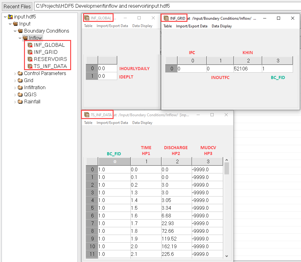
Boundary Conditions
Inflow
Defines the location and time series for inflow hydrographs.
Corresponds to: INFLOW.DAT
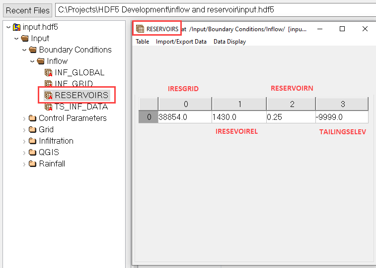
Reservoirs
Specifies the reservoir nodes, elevations and a manning’s n value corrector.
Corresponds to: INFLOW.DAT
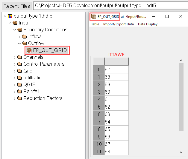
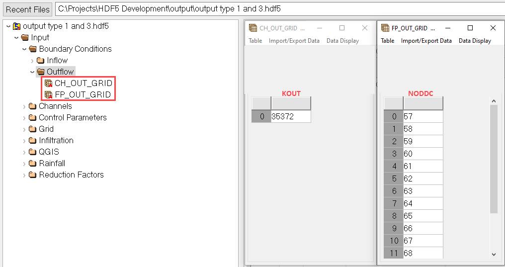
Outflow
Floodplain Normal Depth
Corresponds to: OUTFLOW.DAT
Defines rating curve or normal depth outflow control for floodplain cells.
Channel Normal Depth
Normal depth outflow control for channels.
Floodplain Time Stage
Time-series stage boundary for floodplain grid cells.
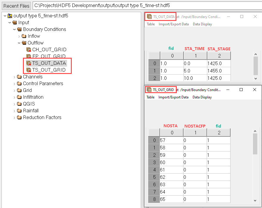
Floodplain and Channel Time Stage
Combined time-stage outflow control affecting both domains.
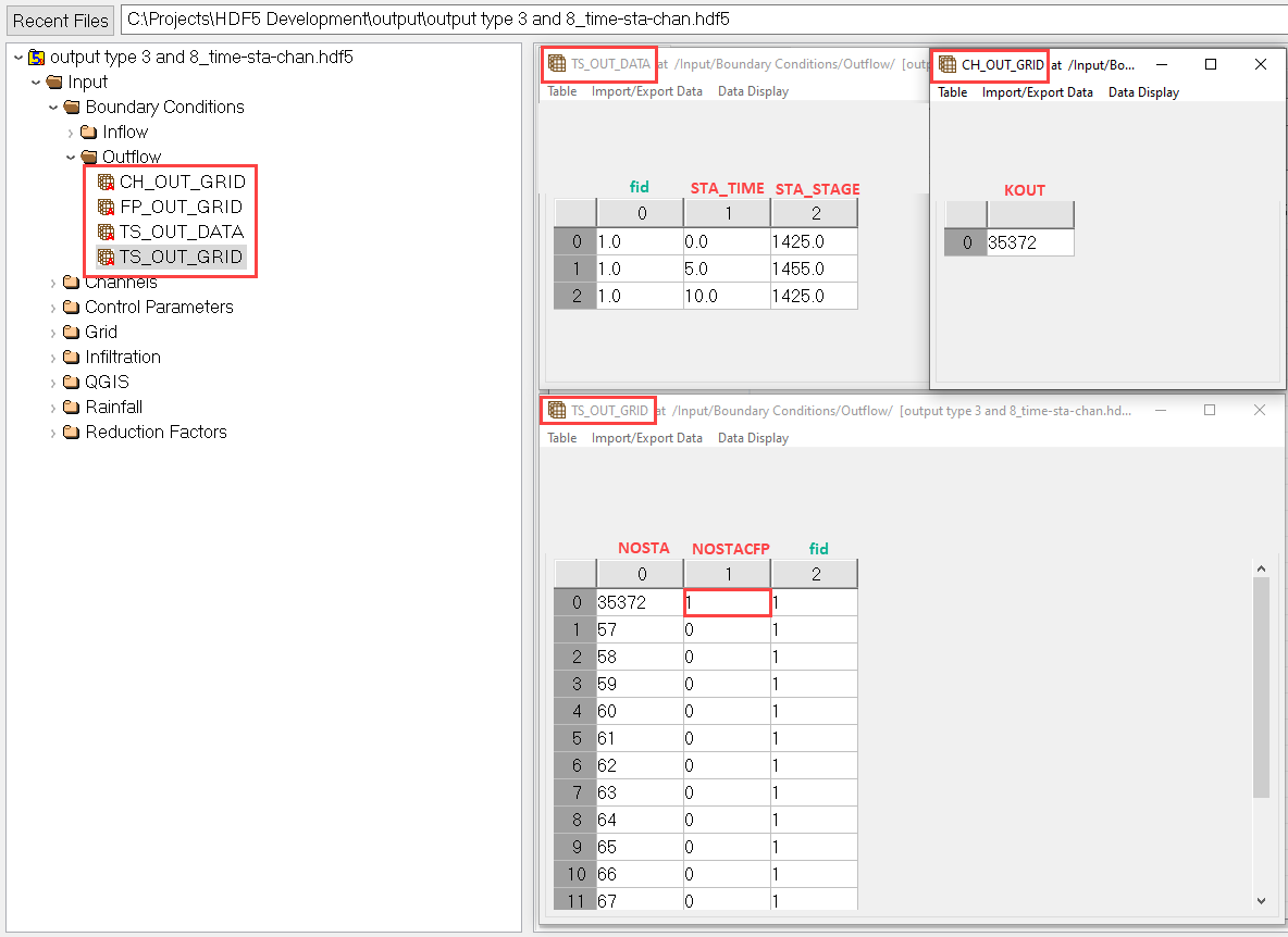
Channel Time Stage
Time-stage boundary applied to channel outflows.
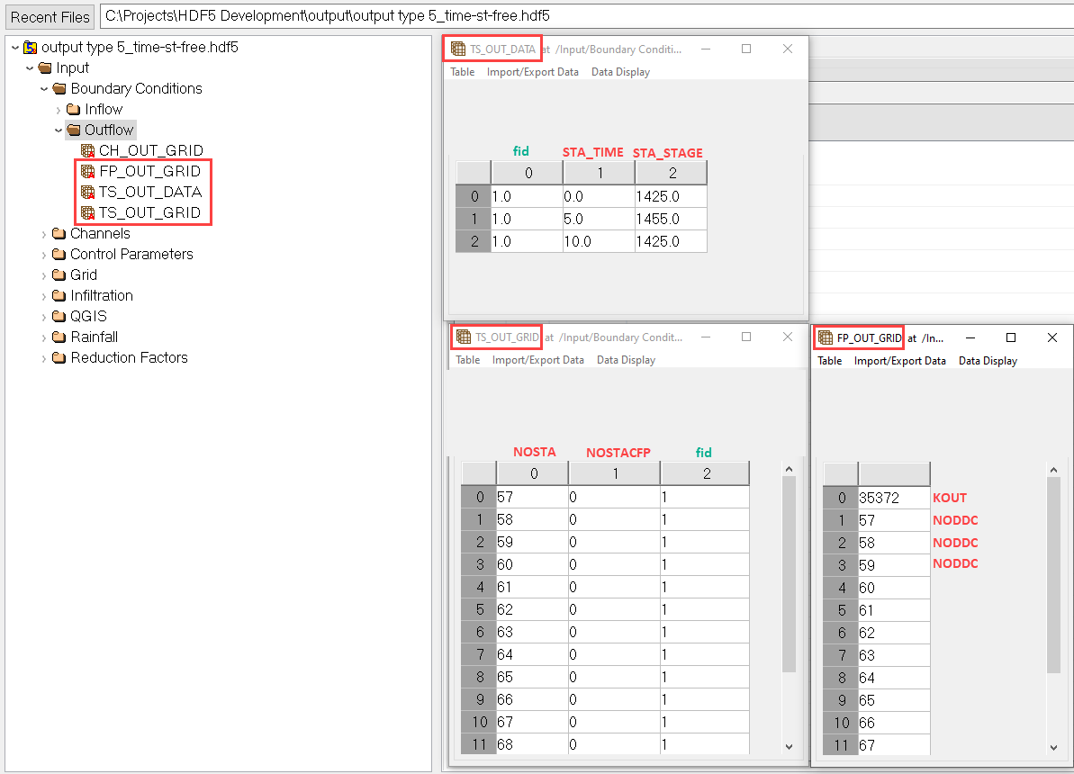
Floodplain and Channel Time Stage and Free
Free outflow combined with a time-stage control.
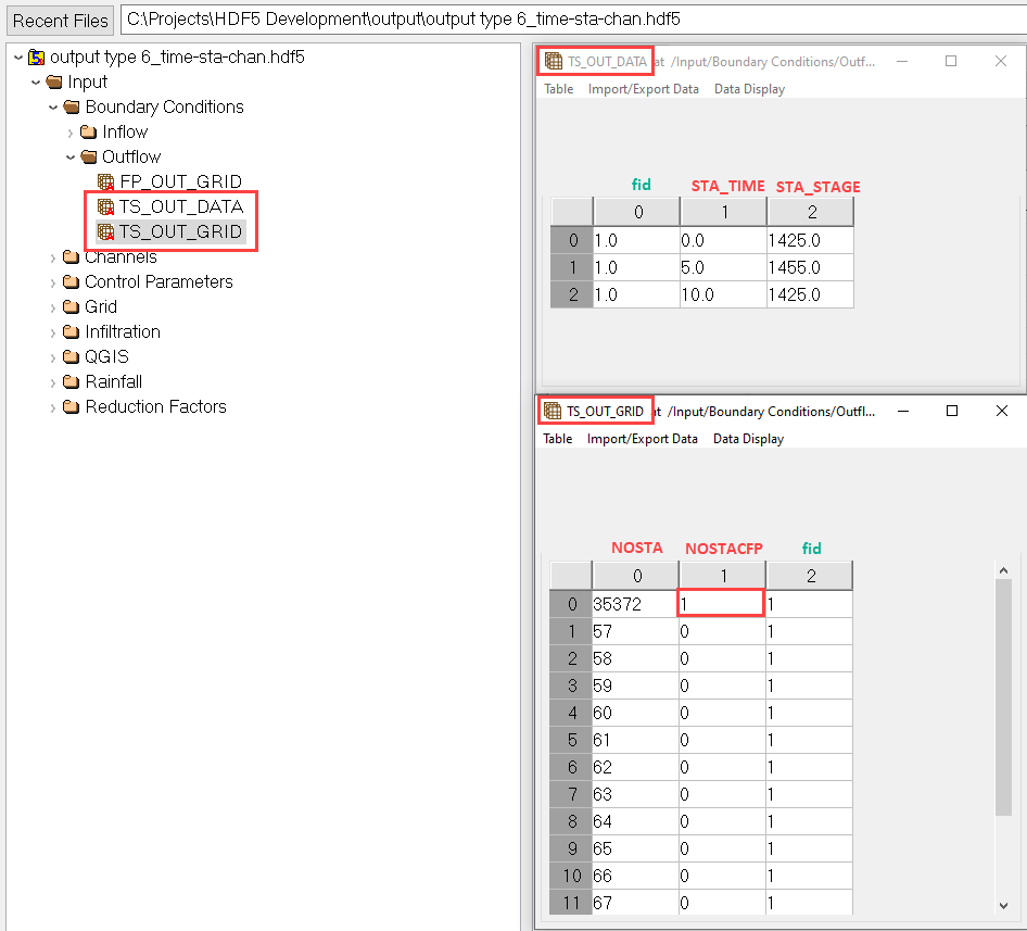
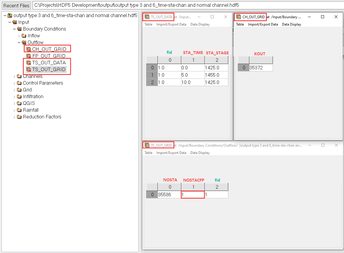
Channel Time Stage and Normal
Combines stage-based control with a normal depth fallback.
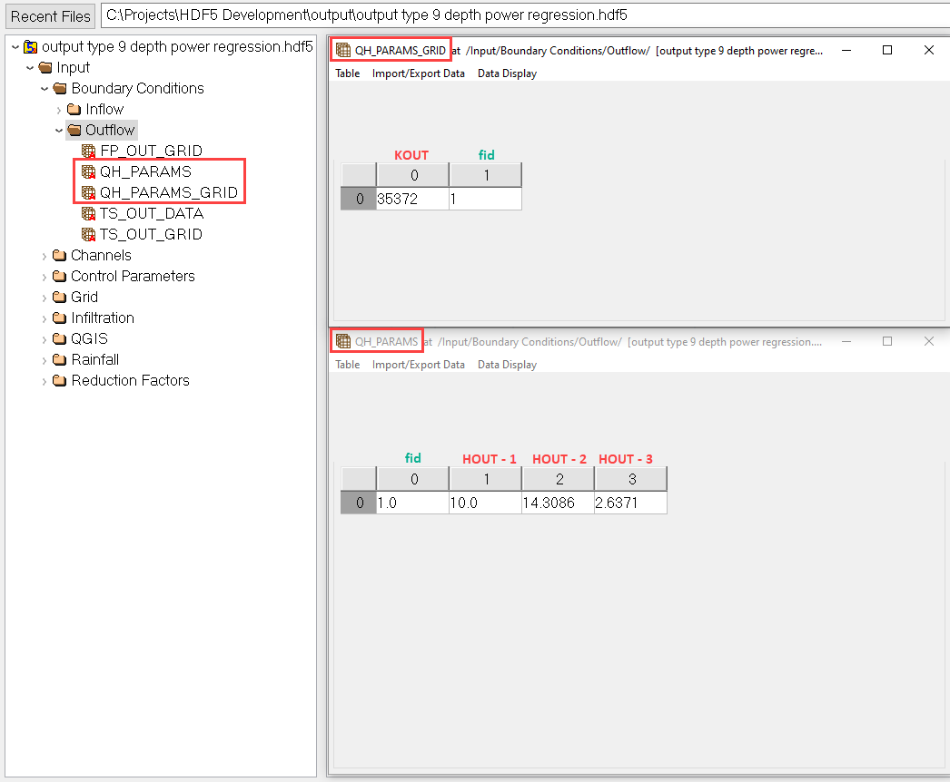
Channel Depth-Discharge Power Regression
Defines outflow using regression coefficients.
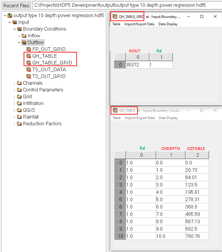
Channel Depth-Discharge Table
Tabulated depth-discharge pairs for outflow control.
Channels
Global
All 1D channel data will have a control data and bank data.
Corresponds to: CHAN.DAT, CHANBANK.DAT
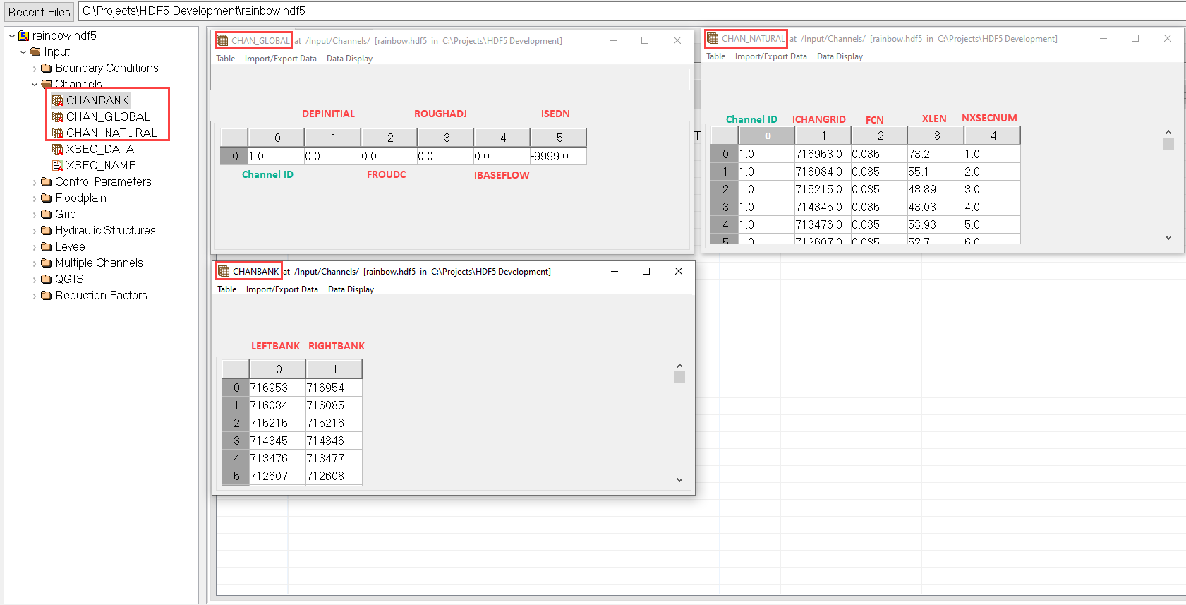
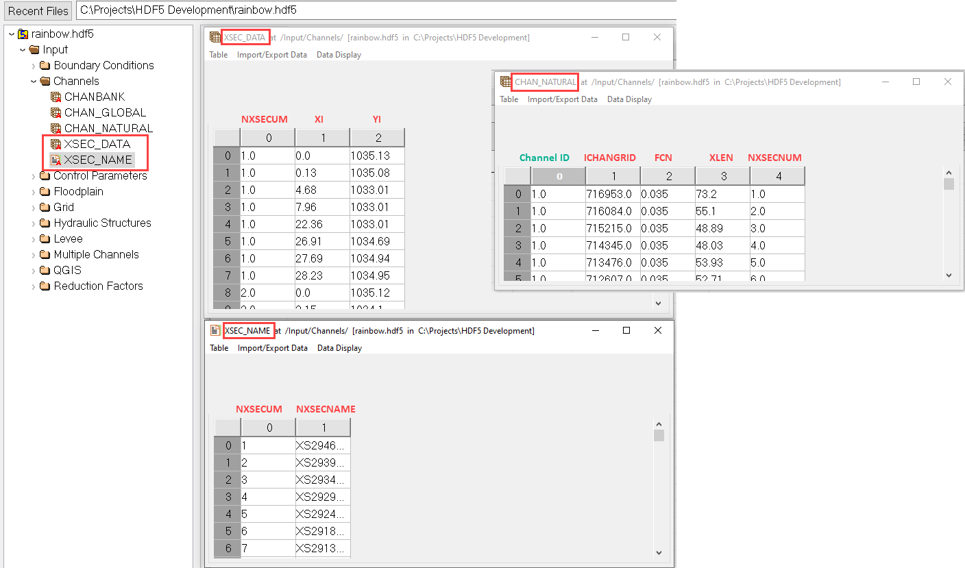
Channel Natural
Channel cross reference and and cross section station elevation data.
Corresponds to: CHAN.DAT, XSEC.DAT
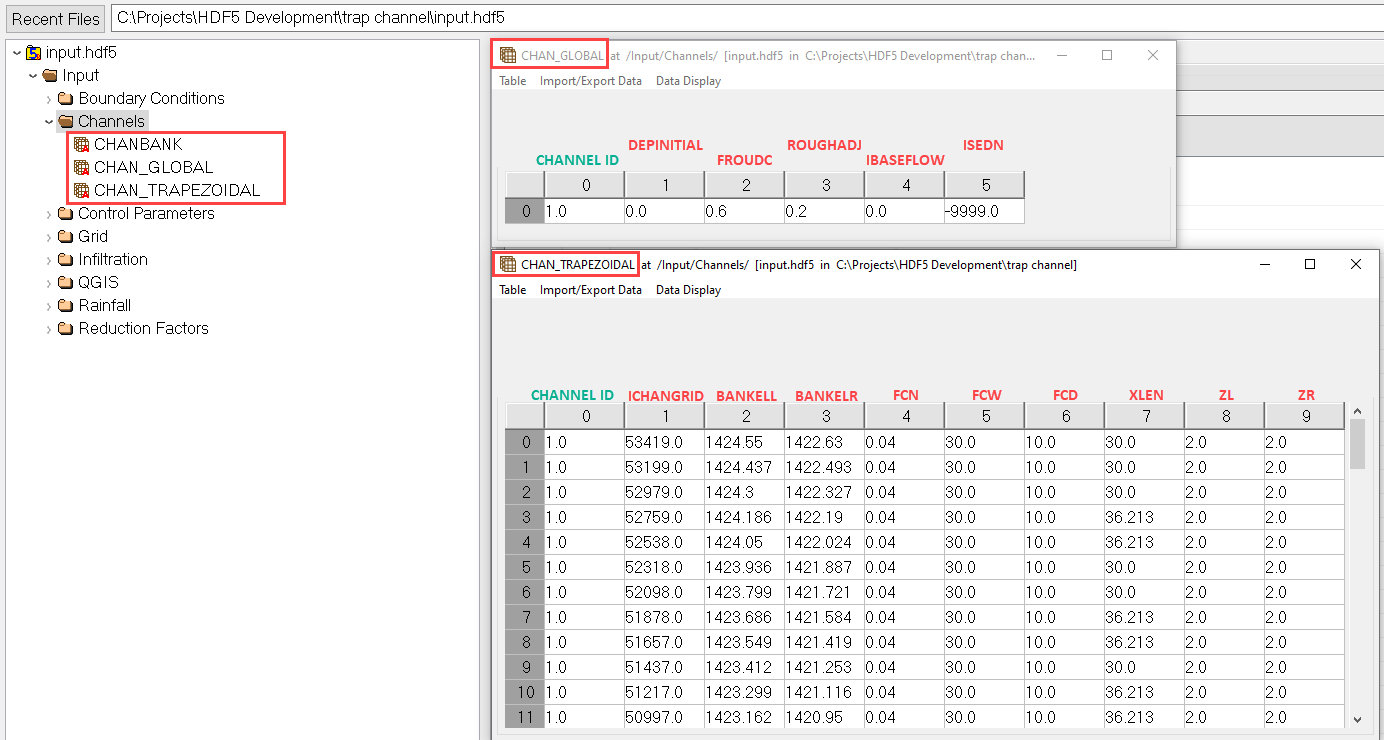
Channel Trapezoidal
Defines trapezoidal cross sections using base width, depth, and side slope.
Corresponds to: CHAN.DAT
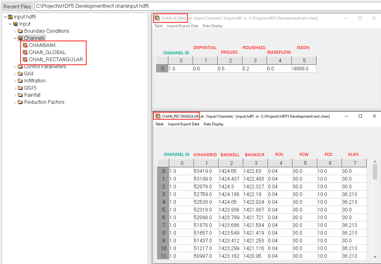
Channel Rectangular
Defines rectangular cross sections using base width and depth.
Corresponds to: CHAN.DAT
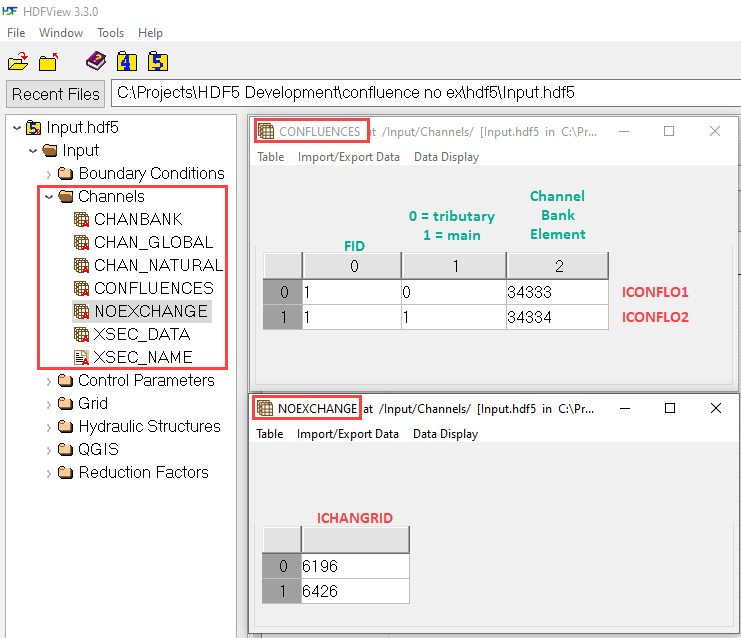
NoExchange / Confluence
Reserved for special conditions like confluence or split flow and no exchange condition between the channel and floodplain.
Corresponds to: CHAN.DAT C lines and E lines.
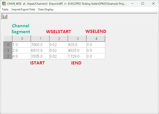
Starting Water Elevation
Reserved for special conditions where a channel needs a water surface elevation to be applied between two channel elements within the same channel segment.
Corresponds to: CHAN.DAT Lines 3a and 3b.
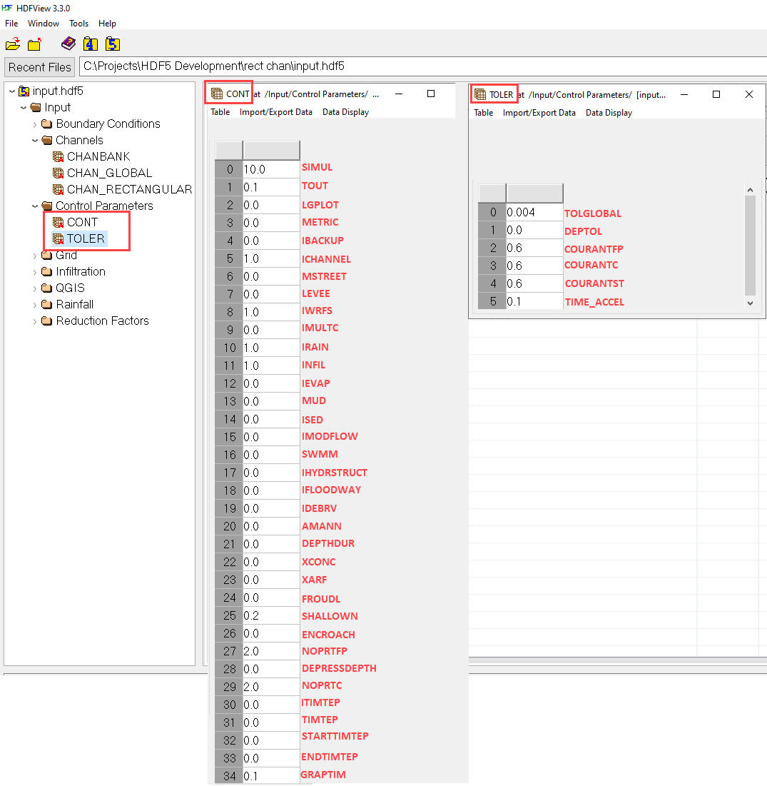
Control Parameters
Contains global control data and switches and numerical tolerances.
Corresponds to: CONT.DAT, TOLER.DAT
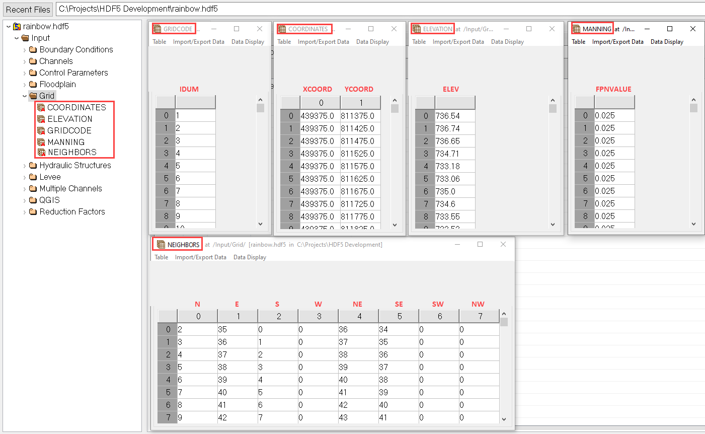
Grid
Defines spatial layout and surface properties.
Corresponds to: TOPO.DAT, MANNINGS_N.DAT, CADPTS.DAT, FPLAIN.DAT, NEIGHBORS.DAT
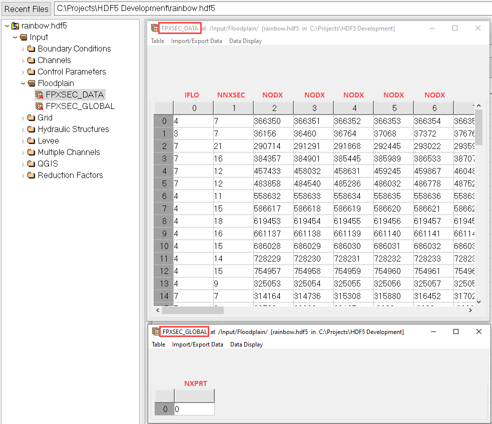
Floodplain Cross Section
Defines cross section grid elements that are reported to cross section output files.
Corresponds to: FPXSEC.DAT
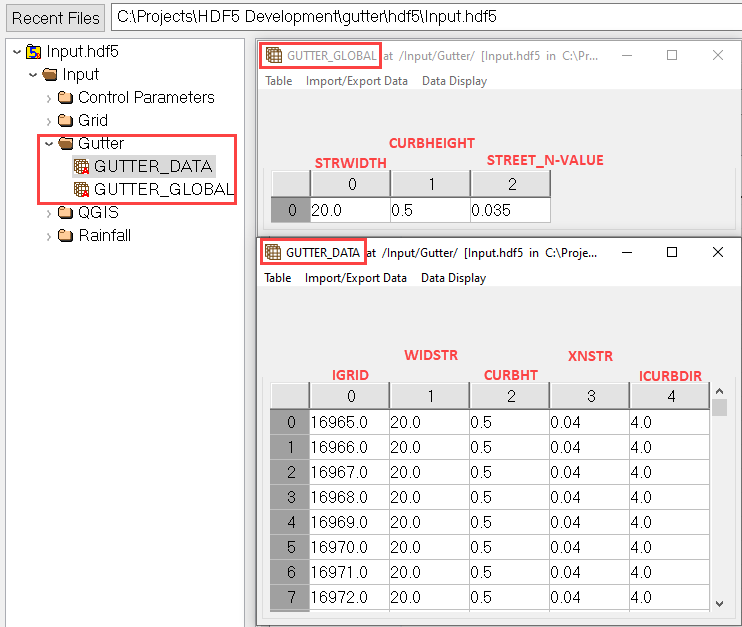
Gutter
Defines gutter parameters.
Corresponds to: GUTTER.DAT
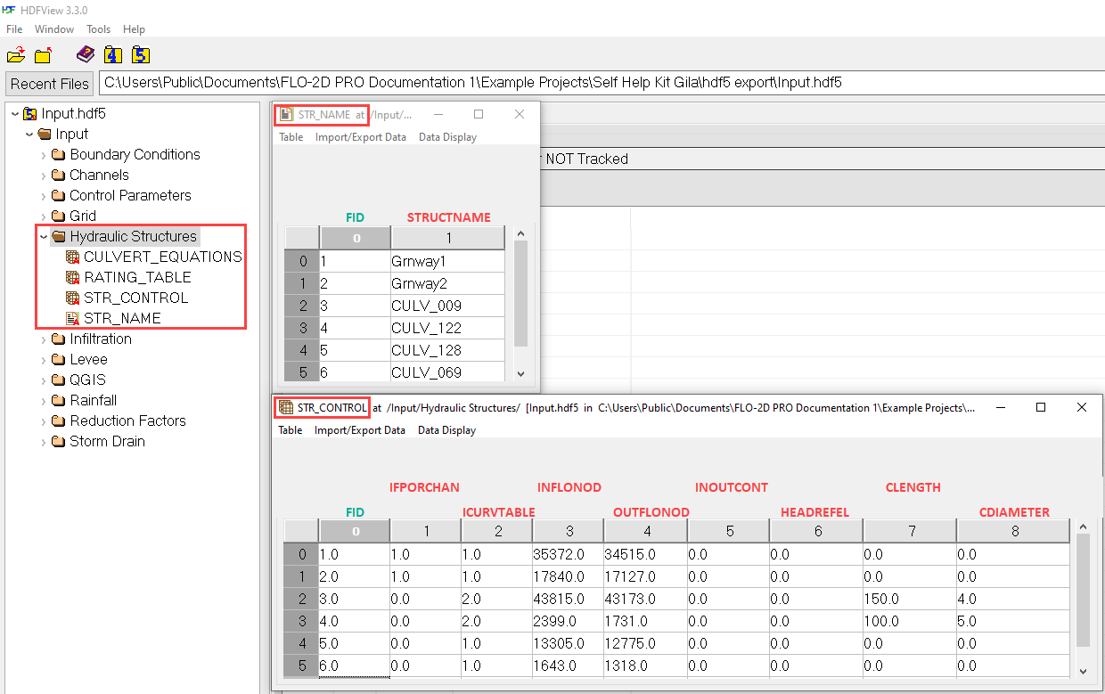
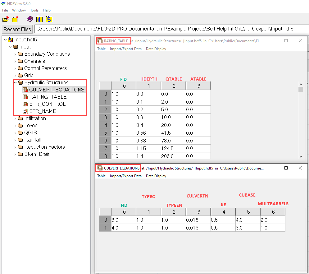
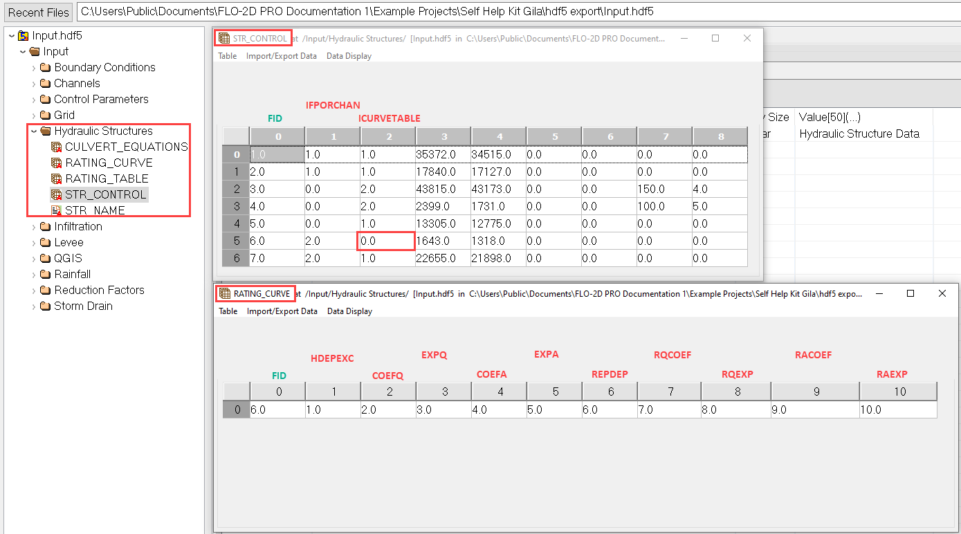
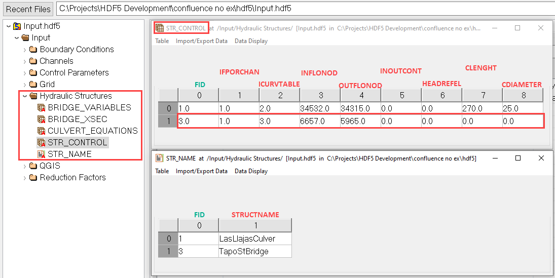
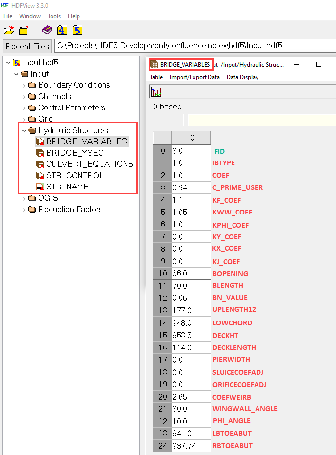
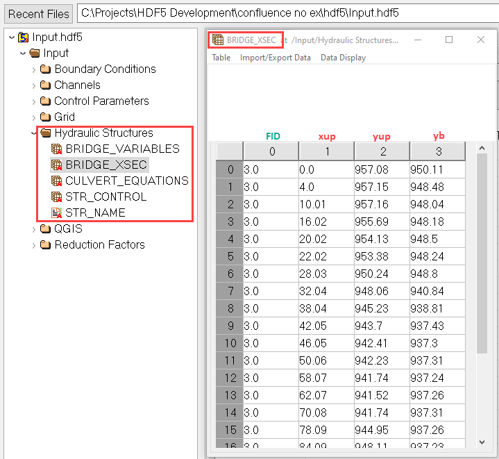
Hydraulic Structures
Hdf5 data for hydraulic structures is organized into several tables, each corresponding to a specific structure type or function.
Corresponds to: HYSTRUC.DAT, BRIDGE_XSEC.DAT, BRIDGE_COEFF.DAT
Control tables and name tables.
Depth Discharge Tables and Culvert Equation Tables.
Rating curve and replacement curve tables.
Bridge tables parameters and cross section data.
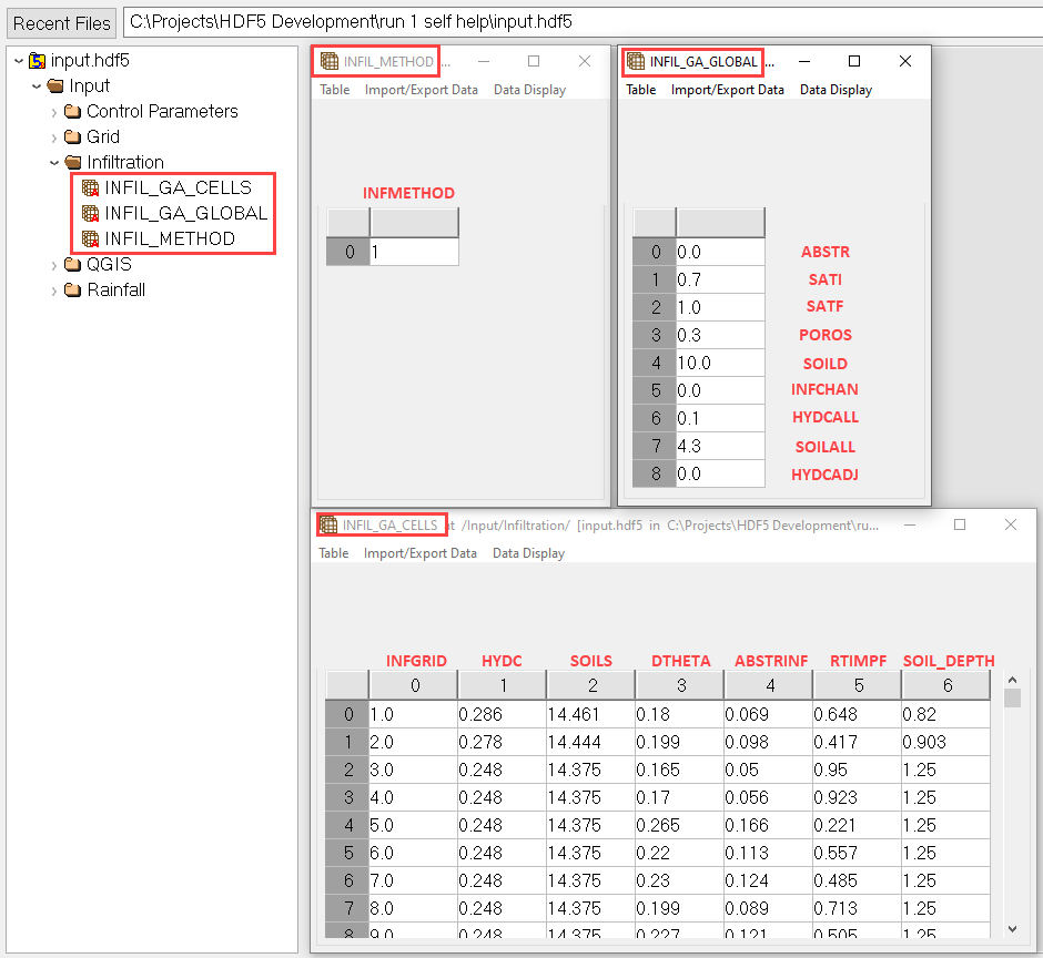
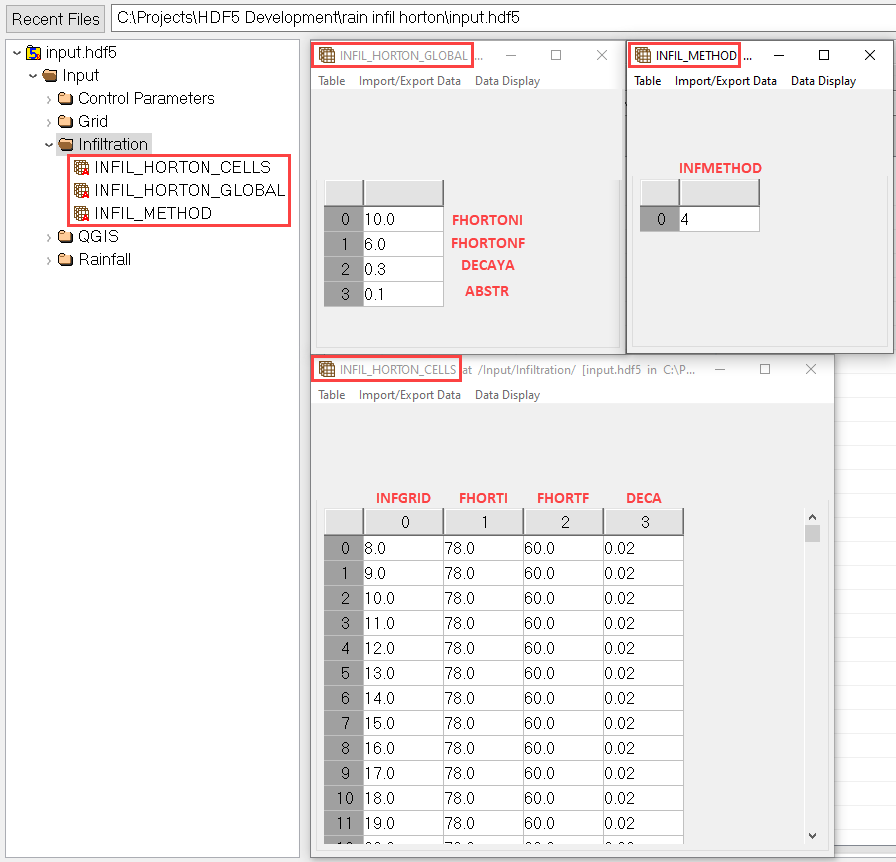
Infiltration
Infiltration data is organized into several tables, each corresponding to a specific infiltration method or parameter set.
Corresponds to: INFIL.DAT
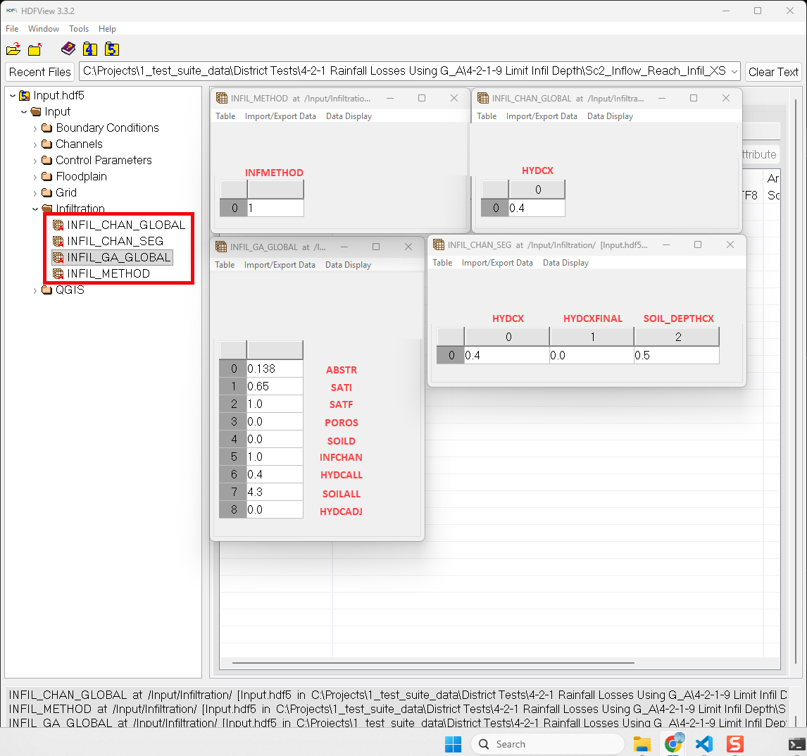
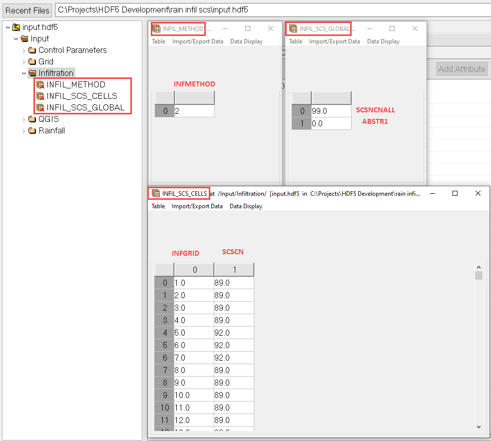
Method
Defines the selected infiltration method: Green-Ampt, SCS, or Horton.
Green Ampt
Defines Green-Ampt infiltration parameters spatially or globally.
Green Ampt Channel
Single channel infiltration.
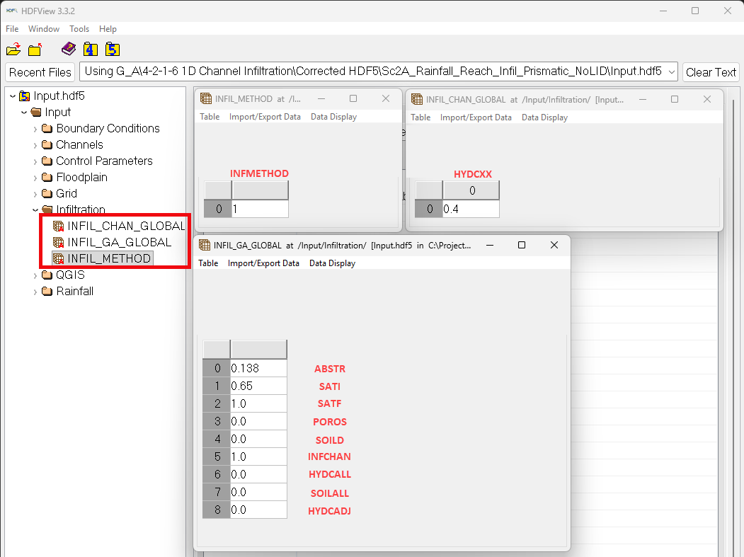
Channel infiltration by reach.
SCS Curve Number
Defines SCS curve number infiltration parameters spatially or globally.
Horton
Defines Horton infiltration parameters spatially or globally.
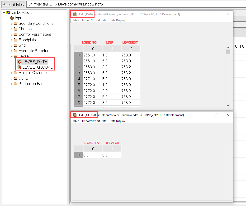
Levee
Defines levee parameters and levee and breach failure parameters.
Corresponds to: LEVEE.DAT
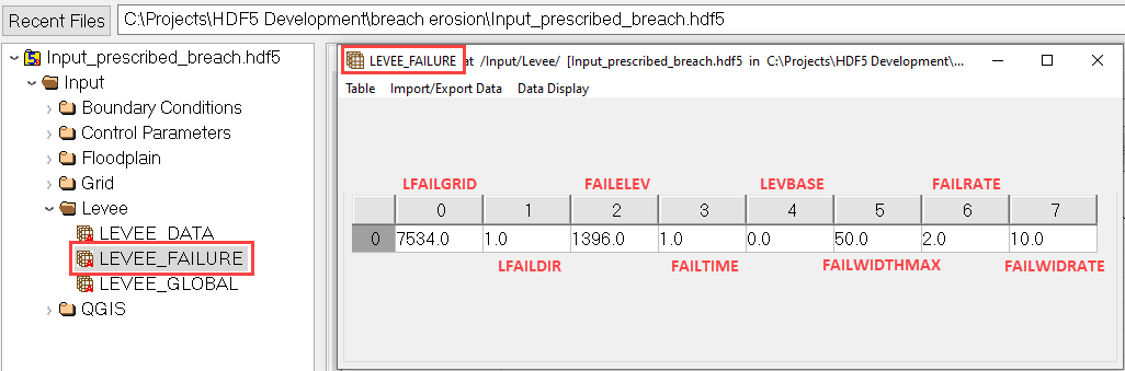
Levee Failure Prescribed
Prescribed levee failure using time of breach and prescribed vertical and horizontal levee failure rates.
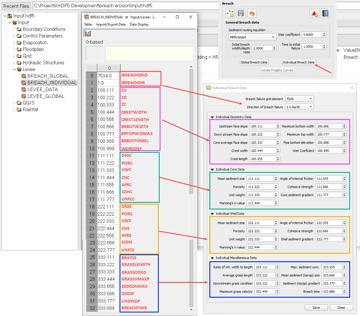
Levee Failure Breach Erosion
Dynamic breach using Fread BREACH method.
Corresponds to: BREACH.DAT
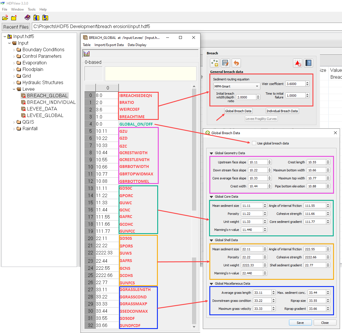
Levee Failure Curve
User-defined breach progression using curve data.
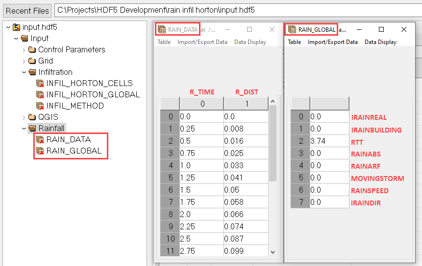
Rainfall
Defines rainfall parameters.
Uniform Rainfall
Applies rainfall uniformly across all grid cells.
Corresponds to: RAIN.DAT
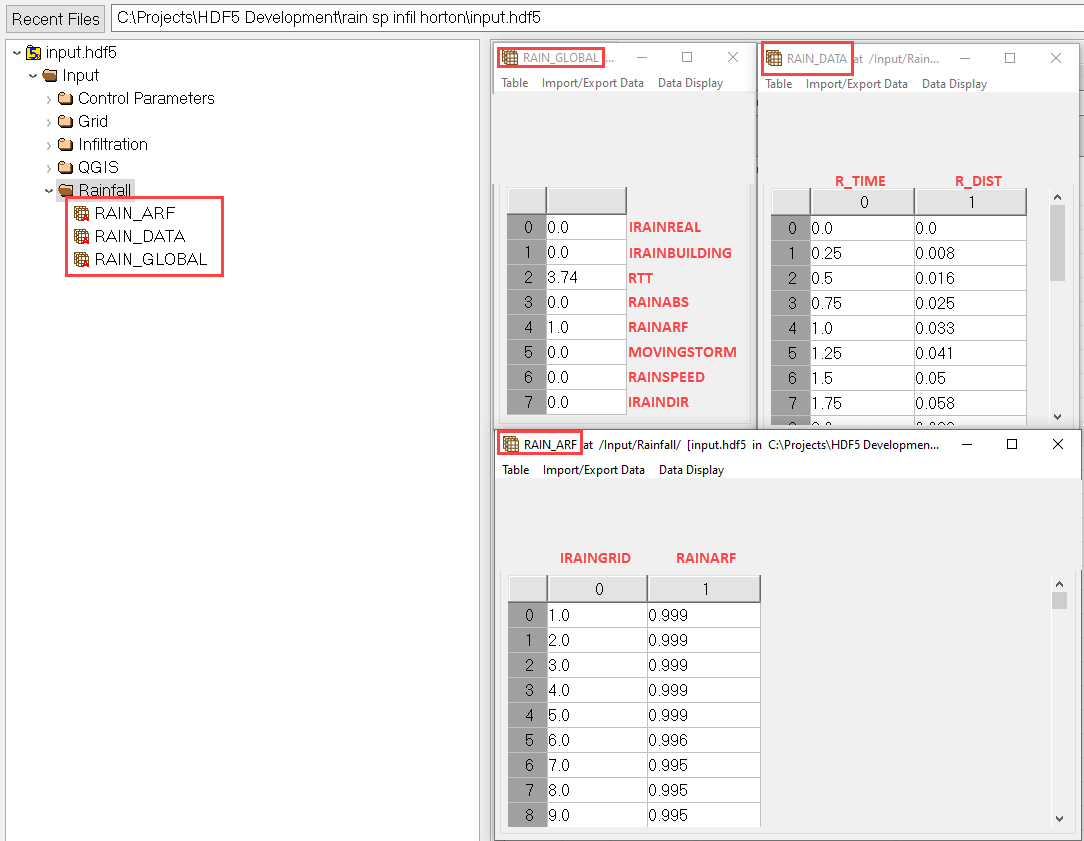
Spatial Rainfall
Applies rainfall using spatial rainfall depth distribution.
Corresponds to: RAIN.DAT
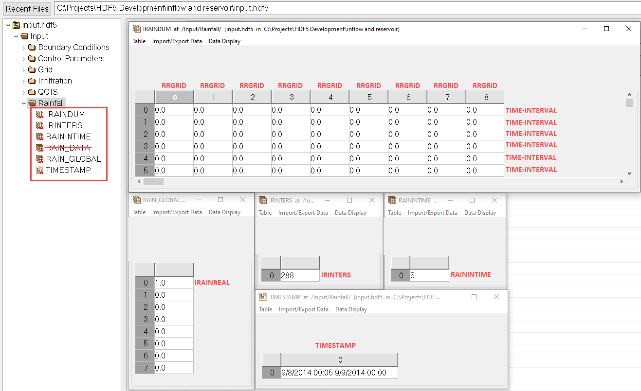
Realtime Rainfall
Uses real-time precipitation from gridded time series.
Corresponds to: RAIN.DAT, RAINCELL.DAT
Note: IRAINDUM table is organized by grid columns x time rows.
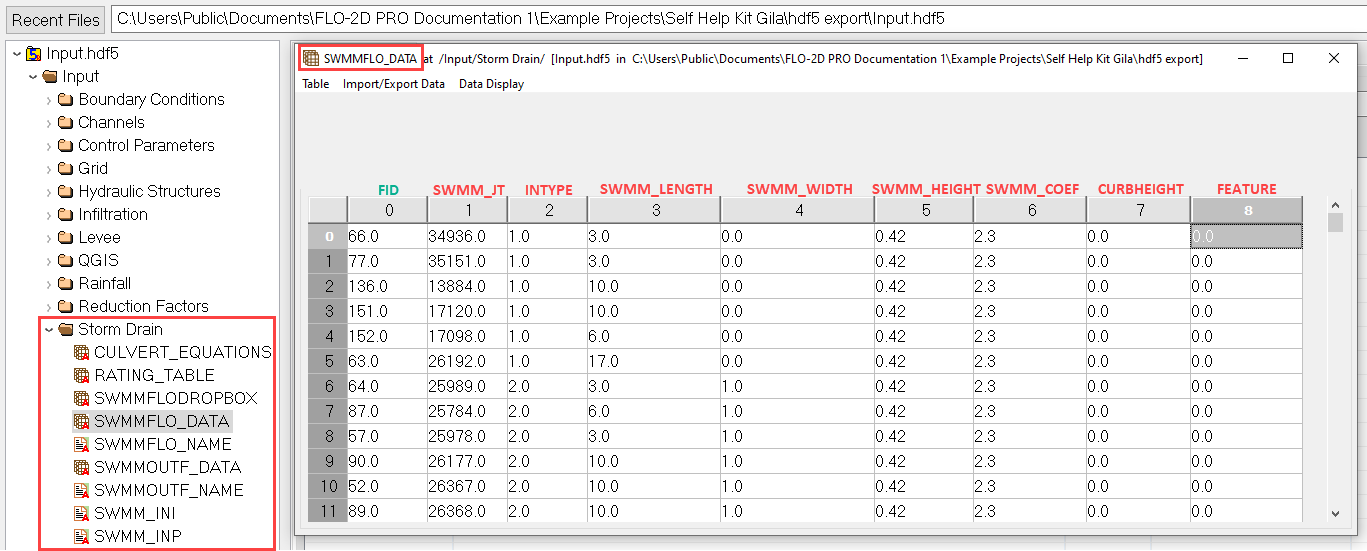
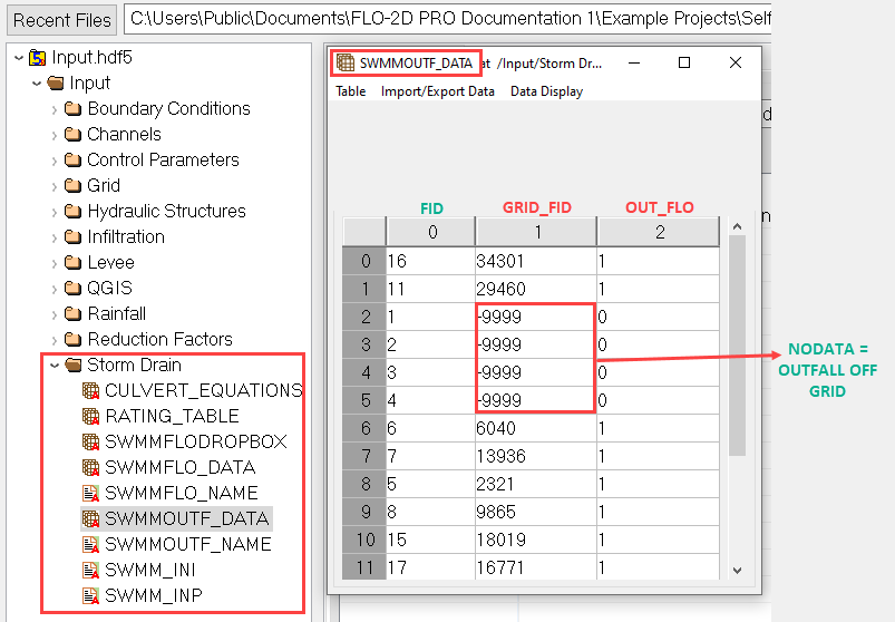
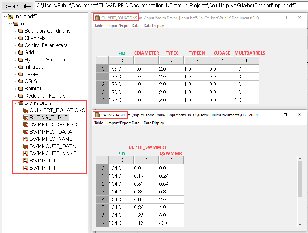
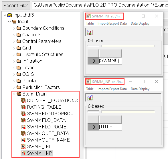
Storm Drain
The storm drain data for HDF5 can be cross referenced to the storm drain files in the Data Input Manual. All other data is saved to the SWMM.INP and SWMM.INI files. The storm drain data is saved to the HDF5 file in the following tables:
Corresponds to: SWMMFLO.DAT, SWMMOUTF.DAT, SWMMRT.DAT, SWMMFLODROPBOX.DAT, SDCLOGGING.DAT
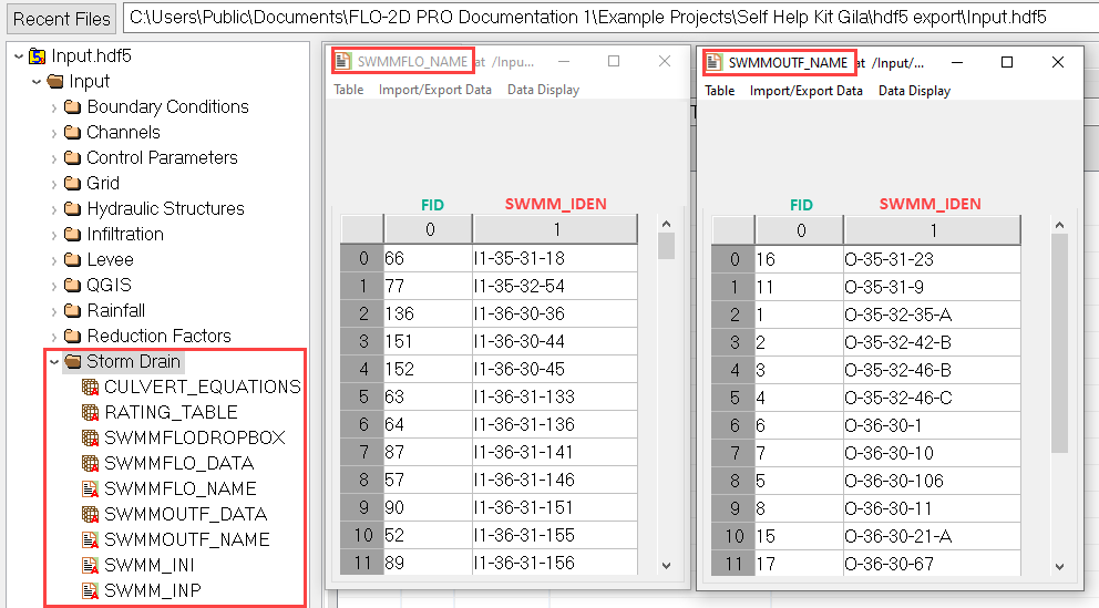
Corresponds to: SWMMFLO.DAT
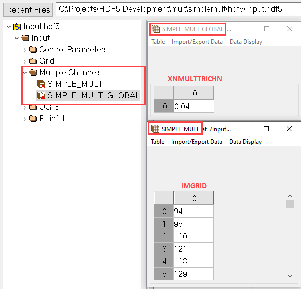
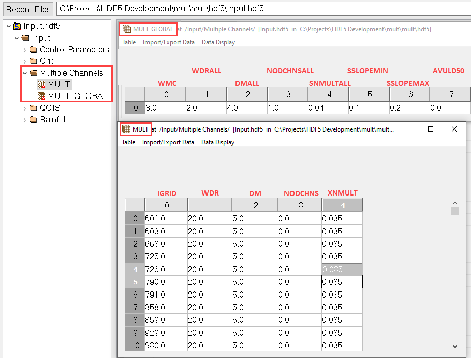
Multiple Channel
The multiple channel data for HDF5 can be cross referenced to the multiple channel files in the Data Input Manual.
Corresponds to: MULT.DAT, SIMPLE_MULT.DAT
Multiple Channel Legacy Method
Corresponds to: MULT.DAT
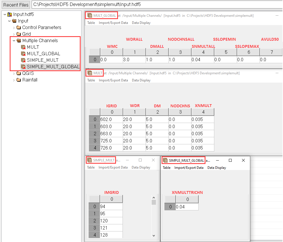
Multiple channel simple method
Corresponds to: SIMPLE_MULT.DAT
Multiple channel combined method.
Corresponds to: MULT.DAT, SIMPLE_MULT.DAT
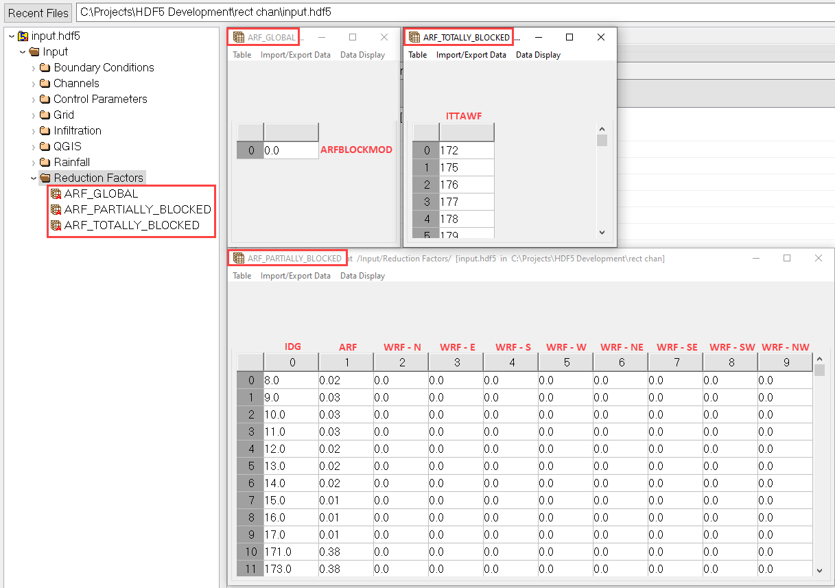
Reduction Factors
Defines blocked cells for buildings and other obstructions.
Corresponds to: ARF.DAT
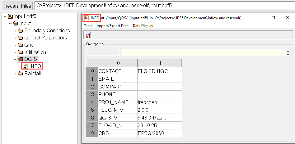
QGIS
Modeller contact info and FLOPRO, Plugin, and QGIS version information.
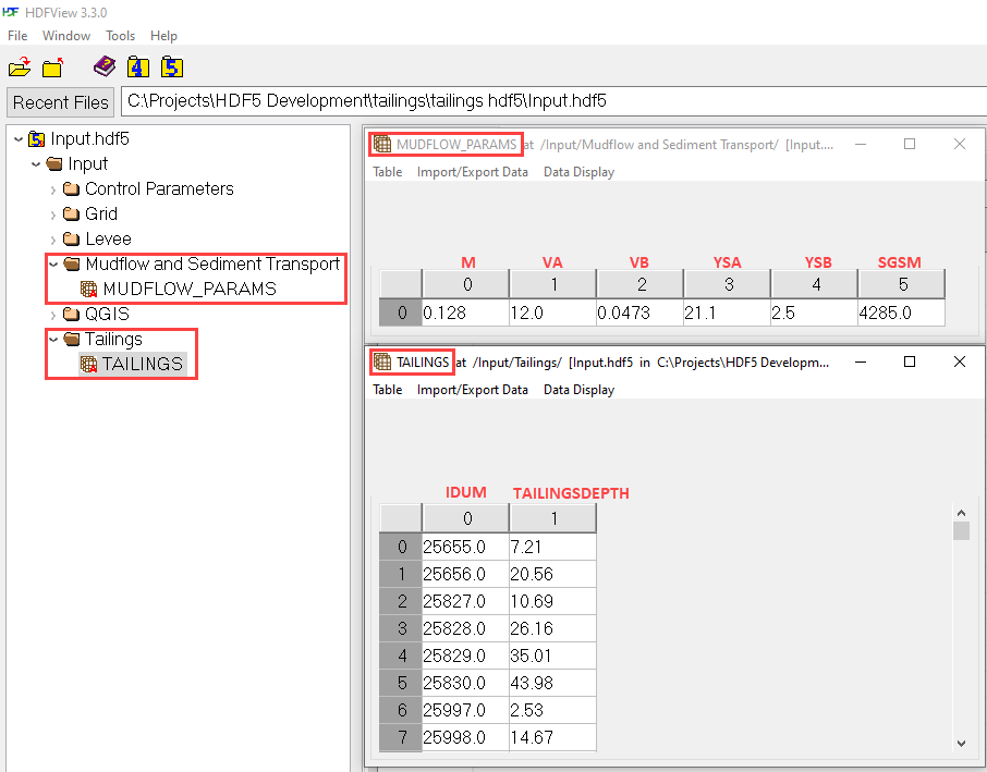
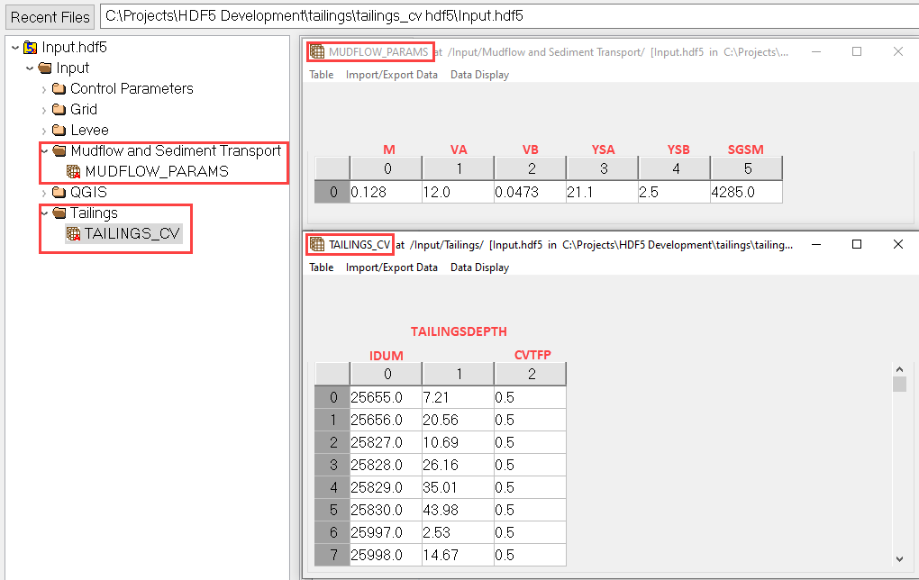
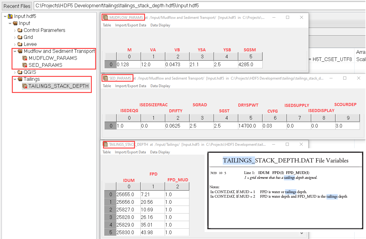
Tailings
Defines tailings depth parameters, tailings depth and cv parameters, and tailings stack depth parameters.
TAILINGS Corresponds to: TAILINGS.DAT
TAILINGS_CV Corresponds to: TAILINGS_CV.DAT
TAILINGS_STACK_DEPTH Corresponds to: TAILINGS_STACK_DEPTH.DAT
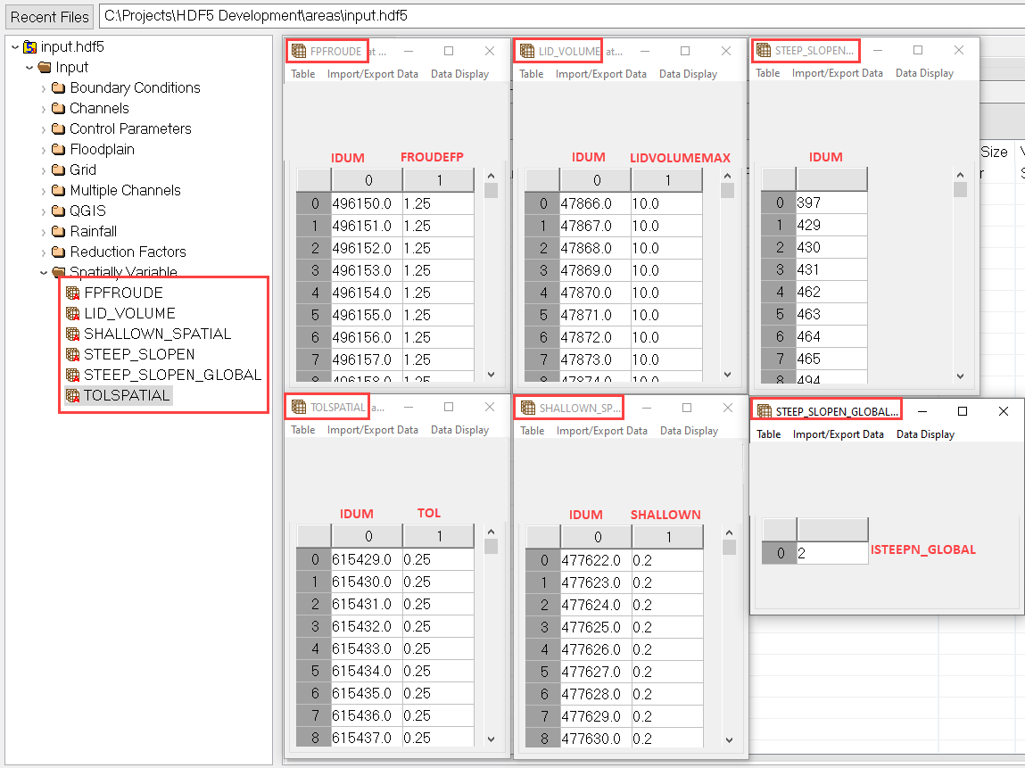
Spatially Variable
The 2D attributes for FLO-2D are stored in the Spatially Variable tables. The table name can be cross referenced to the corresponding *.DAT file in the Data Input Manual.
FPFROUDE Corresponds to: FPFROUDE.DAT
LID_VOLUME Corresponds to: LID_VOLUME.DAT
SHALLOWN_SPATIAL Corresponds to: SHALLOWN_SPATIAL.DAT
STEEPSLOPEN Corresponds to: STEEP_SLOPEN.DAT
TOLSPATIAL Corresponds to: TOLSPATIAL.DAT