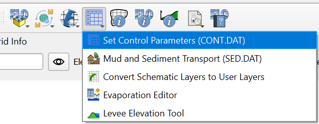
Set Control Parameters (CONT.DAT)
This button allows the user to set up the control variables. The variable descriptions and instructions are available in the Data Input Manual.
See the Data Input Manual 2025 for more details.
Control Parameters
Click the Set Control Parameters (CONT.DAT) button. This dialog box is used to set the control parameters for each simulation.
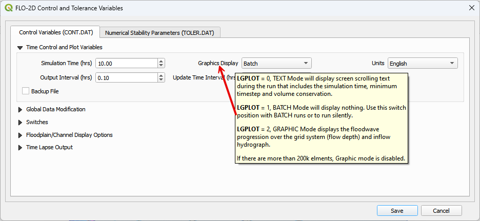
Time Control and Plot Variables
Use this group of variables to define the simulation properties like simulation time and output interval.
Hover over any variable label to get a description in the tooltip.
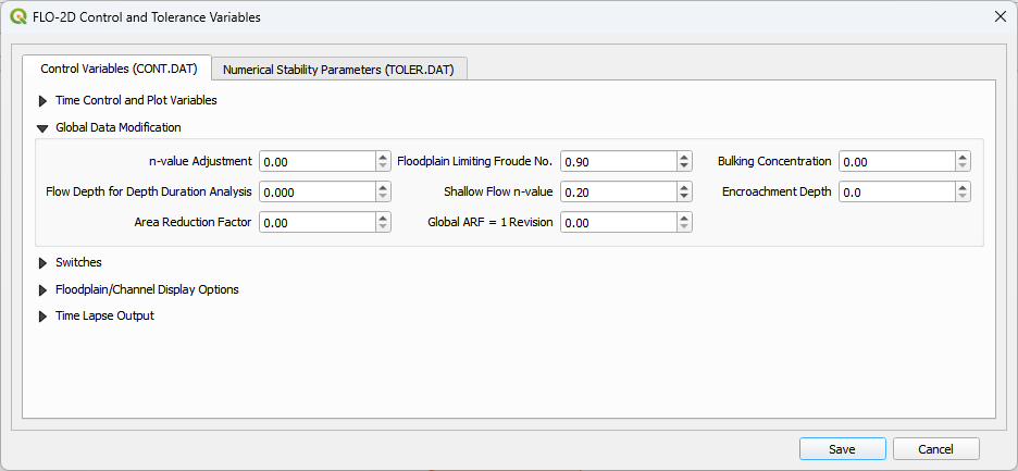
Global Data Modification
Global variables can be applied to all elements in the grid system.
Note
The Global ARF = 1 Revision is written to the ARF.DAT file.
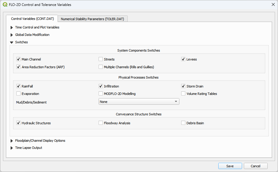
Switches
Set up on off switches for modeling specific processes. Don’t turn on the switches until the data has been set up for each process.
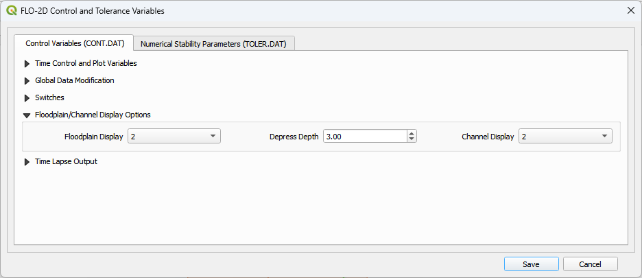
Floodplain / Channel Display Options
The floodplain and channel switches will write more data to the base.out file when turned on. The default is off (2). Keep them off unless troubleshooting specific processes or reviewing data on a timestep basis.
The Depress Depth (ft or m) is used to help find grid elements that have an elevation that is more than 3 ft lower lower than all of its neighbors.
The Depress Depth variable is also used to help find levees that have a crest elevation that is too close to the grid elevation.
Depress Depth used to be called super.out. If trying to load a project in GDS, set this variable to 0 so GDS can load it.
Time Lapse Output
Time-lapse output writes data to multiple output files (for example, TIMDEP.OUT).
Time-lapse switch behavior has evolved across software builds. Refer to the Data Input Manual for build-specific details.
Build 25 introduces new functionality for switch positions 3 and 4.
Uncheck the Use Time Interval option when the full simulation duration is to be processed.
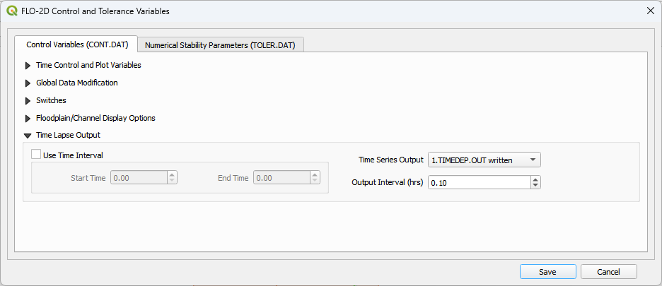
Configure the time-lapse switch settings prior to running the model.
Output files generated by these switches can be large; use discretion when enabling them.
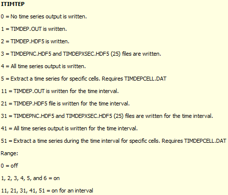
ITIMTEP — Time-Dependent Grid Output
The ITIMTEP switch controls whether FLO-2D writes time-dependent grid
output, which output formats are written, and (in newer builds) the time
interval during which output is produced.
Behavior by Build
Build |
ITIMTEP Behavior |
|---|---|
≤ Build 14 (2015) |
|
Build 16 (2016–2017) |
Output format selection introduced.
|
Builds 18 (2018–2019) |
Same output behavior as Build 16.
Cell-specific time-series extraction added:
|
Builds 19 (2019–2020) |
Minor output variations introduced.
Cell-specific time-series extraction retained:
|
Build 21 (2021–2022) |
Transitional and internally complex behavior driven by early QGIS time-series integration.
|
Build 23 (2022–2025) |
Output format selection simplified.
Interval-controlled output formally introduced:
|
Build 25 (2026+) |
Output format selection refined.
Interval-controlled output retained:
|
Backward Compatibility Notes
Note
Projects created with FLO-2D builds prior to Build 15 treat
ITIMTEP as a simple enable/disable flag. A 1 value
activates ASCII TIMDEP.OUT.
Interval-based ITIMTEP values (11, 21, 31, 41, 51) will not work for
builds earlier than Build 23.
When upgrading legacy projects, review ITIMTEP settings to ensure
that output formats and interval behavior match the intended build
capabilities.
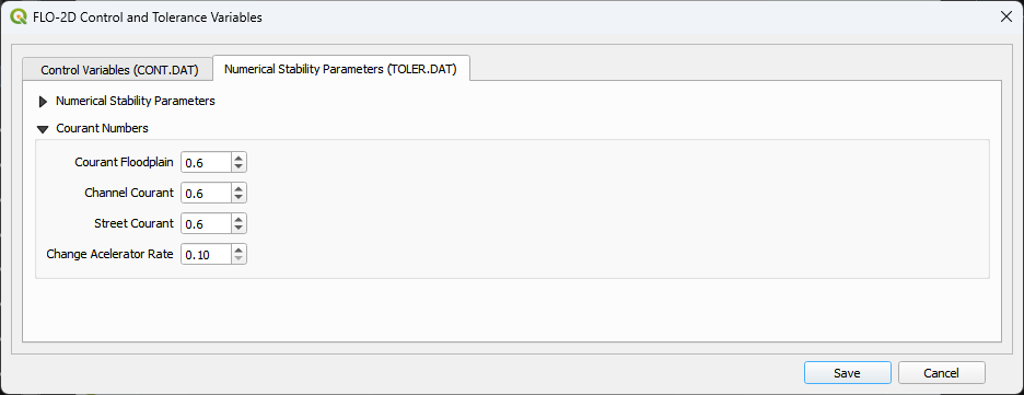
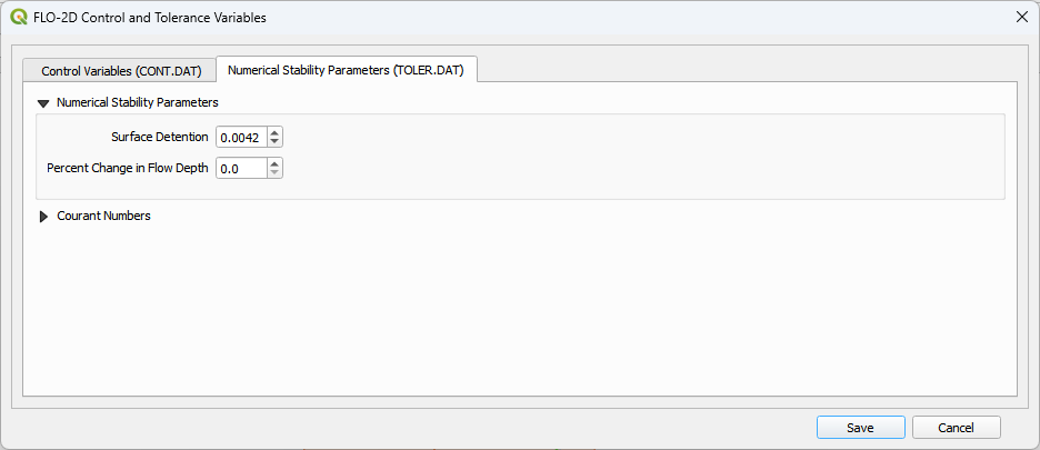
Numerical Stability
Numerical stability parameters are defined on the second tab.
Numerical stability parameters. These parameters are used to control the numerical stability of the model. The values are set based on the grid size and the flow conditions. See the Data Input Manual for more details.
Note
The wavemax variable has been removed from this version of the FLO-2D Plugin. The variable hasn’t been used in a long time but it was maintained as a place holder. If you have a toler.dat with a wavemax > 0.00, you likely have a project that is FLO-2D v2007 or earlier. Get tech support to help identify which build was used for your project.
Contact us to find the correct which version you may have.
Courant Numbers
The Courant numbers are used to control the numerical stability of the model. The values are set based on the grid size and the flow conditions. See the Data Input Manual for more details.