5. Chapter 5: Output Files and Options
5.1. Basic Guidelines for Using Output Files.
During the flood simulation, the user has two choices for viewing the model flood progression:
An output text screen
A graphical representation of the flood simulation.
The screen option is selected with the LGPLOT variable in the CONT.DAT file. The text screen scrolls a list of the simulation time, minimum timestep and the volume conservation data. This screen enables the user to view the simulation runtime speed and the volume conservation. The second screen option is a color graphics display of the grid element flow depth (area of inundation) along with the inflow hydrograph. After the flood simulation is complete, the hydraulic results are presented in output files that contain hydrographs, maximum flow depths and velocities.
The conservation of flood volume (inflow equals outflow plus storage) should be reviewed for each simulation. A summary of the inflow volume, final volumes left on the floodplain (storage) and outflow from the grid system is presented in the SUMMARY.OUT file.
Output files are created with both spatial and temporal formats. Output files that are listed in the order of the output intervals are temporal output and output files listed in the order of the grid elements is spatial output. Output data include water surface elevation, flow depth, velocity, discharge, impact pressure, specific energy, sediment concentration and other variables. Overland flow hydraulics may be viewed as individual grid elements or the grid elements can be grouped together to produce floodplain cross-sections. Summary tables listing maximum velocity and flow depths and their times of occurrence appear at the end of the BASE.OUT file. Review the CONT.DAT file description in Chapter 4 for more information about specifying output file formats.
The user is cautioned about specifying the output in too much detail which can result in extremely large output files. The output time interval TOUT and NOPRTFP options in the CONT.DAT file can be assigned to limit the size of the output files. When NOPRTFP is set to 0, all the floodplain output data is written to the BASE.OUT file for each output interval. Setting NOPRTFP = 2 will turn off all of the temporal floodplain hydraulic output data.
The user does not have to specify any output file names. It is important to note that each time the model is run, it will write over the existing output files and the previous output file data will be lost. To save any output files in anticipation of subsequent simulation, the user should create another subdirectory.
Use NotePad© , NotePad++© or any other ASCII editor to view the output files. A brief description of all the output files follows:
Table 5.1. List of General *.OUT Files and Unit Numbers
File No. |
File Name |
File No. |
File Name |
2 |
BASE.OUT |
19 |
TIME.OUT |
11 |
SUMMARY.OUT |
55 |
SURFAREA.OUT |
Table 5.2. List of 2-D Overland Output
File No. |
File Name |
File No. |
File Name |
Depth |
Velocity |
||
20 |
DEPTH.OUT |
118 |
VELTIMEFP.OUT |
27 |
DEPTHTOL.OUT |
641 |
VELRESMAX.OUT |
28 |
DEPTHDUR.OUT |
81 |
FINALVEL.OUT |
62 |
FINALDEP.OUT |
83 |
FINALDIR.OUT |
60 |
DEPFP.OUT |
63 |
VELDIREC.OUT |
General |
64 |
VELFP.OUT |
|
45 |
FLOODWAY.OUT |
1401 |
VEL_X_DEPTH.OUT |
101 |
IMPACT.OUT |
Discharge |
|
102 |
STATICPRESS.OUT |
105 |
MAXQHYD.OUT |
289 |
INFIL_DEPTH.OUT |
106 |
MAXQBYDIR.OUT |
82 |
OUTNQ.OUT |
107 |
MAXQRESOLVED.OUT |
92 |
INTERGWS.OUT |
124 |
MAXWSELEV.OUT |
67 |
INFILHY.OUT |
Time |
|
104 |
SPECENERGY.OUT |
21 |
TIMDEP.OUT |
111 |
FPINFILTRATION.OUT |
78 |
TIMDEP_NC4.OUT |
Review |
181 |
WSTIME.OUT |
|
1131 |
EVACUATEDFP.OUT |
190 |
TIMETWOFT.OUT |
1597 |
FLOODPLAIN_CONVERGENCE.OUT |
191 |
TIMETOPEAK.OUT |
1598 |
DEPRESSED_ELEMENTS.OUT |
192 |
TIMEONEFT.OUT |
22 |
ROUGH.OUT |
193 |
FLOODWAVETIME.OUT |
65 |
SUPER.OUT |
528 |
DEPTHDUR2.OUT |
288 |
BUILDING_COLLAPSE.OUT |
1921 |
TIME_TO_ABOVE_BASE-FLOW.OUT |
201 |
BASEFLOWFP_TIME.OUT |
Table 5.3. List of 1-D Channel Output
File No. |
File Name |
File No. |
File Name |
14 |
CHANMAX.OUT |
94 |
XSEC.OUT |
24 |
VELOC.OUT |
103 |
CONFLUENCE.OUT |
61 |
DEPCH.OUT |
140 |
CHANSEDSIZE.OUT |
66 |
CHVOLUME.OUT |
113 |
EVACUATEDCHAN.OUT |
74 |
CHNBEDEL.OUT |
117 |
VELTIMEC.OUT |
80 |
HYCHAN.OUT |
261 |
DEPCHFINAL.OUT |
87 |
OVERBANK.OUT |
262 |
VELCHFINAL.OUT |
90 |
CHANSTABILITY.OUT |
263 |
CHAN_INTERIOR_NODES.OUT |
91 |
XSECAREA.OUT |
345 |
CHANLOSSES.OUT |
93 |
CHANWS.OUT |
1596 |
CHANNEL_CONVERGENCE.OUT |
Table 5.4. List of Hydraulic Structures Output
File No. |
File Name |
70 |
HYDROSTRUCT.OUT |
669 |
HYDRAULIC STRUCTURE_RUNTIME WARNINGS.OUT |
910 |
BRIDGE_FLOW_GEOMETRY.OUT |
912 |
BRIDGE_DISCHARGE.OUT |
914 |
BRIDGE_COEFFICIENTS.OUT |
671 |
HYDRAULIC STRUCTURE SUBFACTORS.OUT |
Table 5.5. List of Levee and Breach Output
File No. |
File Name |
File No. |
File Name |
59 |
LEVEE.OUT |
1594 |
LOW_LEVEE_CREST_ELEVATIONS.OUT |
160 |
LEVOVERTOP.OUT |
1601 |
LEVOVERTOPMAX.OUT |
161 |
LEVEEDEFIC.OUT |
1779 |
CVFPMAX.OUT |
255 |
BREACH.OUT |
GE# |
GE#_LEVFAIL.OUT |
1132 |
DAMBREACH_VOLUME.OUT |
699 |
PRESCRIBED_BREACHQ.OUT |
Table 5.6. List of Storm Drain Output
File No. |
File Name |
File No. |
File Name |
1560 |
SWMMQIN.OUT |
1574 |
MANHOLEPOP.OUT |
1565 |
SWMMOUTFIN.OUT |
SWMM.RPT |
|
1563 |
FPRIMELEV.OUT |
SWMM.OUT |
|
1570 |
SD MANHOLEPOPUP.OUT |
Table 5.7. List of Multiple Channel Output
File No. |
File Name |
File No. |
File Name |
25 |
MULTCHN.OUT |
||
205 |
MULTSTEEP.OUT |
Table 5.8. List of Sediment Transport and Mudflow Output
File No. |
File Name |
File No. |
File Name |
17 |
SEDFP.OUT |
88 |
SEDTRAN.OUT |
18 |
SEDCHAN.OUT |
139 |
FPSEDSIZE.OUT |
77 |
SEDCONSERV.OUT |
Table 5.9. List of Two Phase Flow Output
File No. |
File Name |
File No. |
File Name |
241 |
VELOC_MUD.OUT |
831 |
FINALDIR_MUD.OUT |
242 |
CVTMAX.OUT |
811 |
FINALVEL_MUD.OUT |
243 |
CVTMAX_MUD.OUT |
1771 |
FP_BED_CHANGE_MUD.OUT |
245 |
CVTFINAL_MUD.OUT |
1773 |
CVFPMAX.OUT |
361 |
DEPCHFINAL_MUD.OUT |
1775 |
FINALCVFP_MUD.OUT |
602 |
DEPFPMAX_MUD.OUT |
1779 |
CVFPMAX_MUD.OUT |
603 |
DEPTHMAX_2PHASE_COMBINED.OUT |
2070 |
2 PHASE SEDIMENT VOLUME CONSERVATION.OUT |
611 |
DEPCH_MUD.OUT |
2080 |
FPWSEL_MUD.OUT |
622 |
FINALDEP_COMBO.OUT |
6411 |
VELFP_MUD.OUT |
621 |
FINALDEP_MUD.OUT |
6412 |
VELRESMAX_MUD.OUT |
631 |
VELDIREC_MUD.OUT |
Table 5.10. List of MODFLOW Output
File No. |
File Name |
1238 |
MODFLOW FP INFILTRATION VOLUMES.OUT |
1239 |
MODFLOW FP INFILTRATION TOTALS.OUT |
1241 |
MODFLOW CHANNEL INFILTRATION TOTALS.OUT |
1242 |
FLO-2D MODFLOW FP RETURN EXCHANGE.OUT |
1243 |
FLO-2D MODFLOW CH RETURN EXCHANGE.OUT |
1244 |
FPMODFLOWELEV.OUT |
1245 |
CHMODFLOWELEV.OUT |
12466 |
FLO-2D MODFLOW INFILTRATION.OUT |
12477 |
MODFLOW FLO-2D RECHARGE.OUT |
Table 5.11. List of *.RHG Files and Unit Numbers
File No. |
File Name |
File No. |
File Name |
108 |
FPLAIN.RGH |
109 |
CHAN.RGH |
110 |
STREET.RGH |
208 |
MULT.RGH |
309 |
MANNINGS_N.RGH |
1572 |
FPLAIN_SDELEV.RGH |
1573 |
TOPO_SDELEV.RGH |
2229 |
STEEPROUGH.RGH |
Table 5.12. List of Batch Files and Unit Numbers
File No. |
File Name |
File No. |
File Name |
195 |
DEPFP_ANTERIOR.OUT |
213 |
DIFF_VELOC.OUT |
196 |
DIFF_DEPFP.OUT |
214 |
VELTIMEFP_ANTERIOR.OUT |
197 |
FINALDEP_ANTERIOR.OUT |
215 |
DIFF_VELTIMEFP.OUT |
198 |
DIFF_FINALDEP.OUT |
216 |
VELTIMEC_ANTERIOR.OUT |
199 |
ENDRUNBATCHTEST.OUT |
217 |
DIFF_VELTIMEC.OUT |
206 |
VELFP_ANTERIOR.OUT |
218 |
DEPCH_ANTERIOR.OUT |
207 |
DIFF_VELFP.OUT |
219 |
DIFF_DEPCH.OUT |
209 |
DEPTH_ANTERIOR.OUT |
220 |
DEPCHFINAL_ANTERIOR.OUT |
210 |
DIFF_DEPTH.OUT |
221 |
DIFF_DEPCHFINAL.OUT |
212 |
VELOC_ANTERIOR.OUT |
Table 5.13. List of *.TMP Files and Unit Numbers
File No. |
File Name |
File No. |
File Name |
8 |
CHMAX2.TMP |
112 |
OUTNQMAX.TMP |
12 |
OUTNQ.TMP |
122 |
HYSTREET.TMP |
13 |
HYCHAN.TMP |
159 |
LEVOVERTOP.TMP |
15 |
HYCROSS.TMP |
254 |
BREACH.TMP |
16 |
CROSSQ.TMP |
1561 |
SWMMQIN.TMP |
71 |
HYDROSTRUCT.TMP |
1566 |
SWMMOUTFIN.TMP |
76 |
OUTNQ2.TMP |
2 PHASE SEDIMENT VOLUME CONSERVATION.OUT
Summary of the final disposition of the sediment volume.
BASE.OUT
BASE.OUT is an all-inclusive output file. At the beginning of the file, the inflow hydrographs are printed, then the time dependent output data follows.
For each specified time output interval, the flow depth, velocity, water surface elevation and discharge for either the channel or the floodplain grid elements can be written.
The outflow from the boundary grid elements is listed at the end of the time interval.
After the final time output interval, a summary of all the grid elements maximum depths, water surface elevations, velocities and the time of occurrence of the maximum values is printed.
Finally, a summary table of the inflow, outflow and storage volumes at the end of the file allows the user to review the conservation of mass and the ultimate disposition of all the water and sediment.
For convenience, this conservation table is also written to a separate output file named SUMMARY.OUT that is more complete.
There is so much output data in the BASE.OUT file that the user is encouraged to avoid generating this file. All of the text output in this file is provided in individual ASCII xyz output files for plotting purposes and the user will probably have little interest in the BASE.OUT format of the floodplain hydraulics for the individual grid elements.
This output file can become large and it takes too long to write to it for models with 500,000 grid elements or more. Set NOPRTFP = 2 and it will not be created:
If NOPRTFP = 0, all the BASE.OUT floodplain flow data is reported.
If NOPRTFP = 1, the BASE.OUT floodplain outflow data is not reported.
If NOPRTFP = 2, the entire file is not created.
If NOPRTFP = 3, only floodplain outflow data is repIf NOPRTFP = 3, only floodplain outflow data is reported to the BASE.OUT file.
BASEFLOWFP_TIME.OUT
This file provides an option to report the time when the discharge exceeds the floodplain base flow has been implemented. The BASEFLOWFP_ TIME.OUT file reports the following data.
Grid
Xcoord
Ycoord
Time to above baseflow (hrs)
With this output file from a second simulation, the arrival time of an overland floodwave overtaking a base flow is reported. A similar option was coded for channel base flow (uses a B-line with the baseflow in CHAN. DAT on a channel segment basis). The IFLOODWAVE switch is not necessary for reporting the time when the discharge exceeds the channel baseflow. The reporting is activated by the CHAN.DAT B-line.
The floodplain time above baseflow reporting option requires 2 two simulations: 1) Set IFLOODWAVE = 0 in CONT.DAT and prepare INFLOW. DAT with only the base flow hydrographs and run the model. 2) Set IFLOODWAVE = 2 and swap out the INFLOW.DAT file with the flood hydrograph (such as a dam breach hydrograph) and run the model a second time to generate the BASEFLOWFP_TIME.OUT file.
BATCH COMPARISON FILES
Running the batch processor will execute many projects in series and perform automatic comparisons of the output data from previous runs. The following files represent the comparison dataset:
DEPFP_ANTERIOR.OUT
DIFF_DEPFP.OUT
FINALDEP_ANTERIOR.OUT
DIFF_FINALDEP.OUT
ENDRUNBATCHTEST.OUT
VELFP_ANTERIOR.OUT
DIFF_VELFP.OUT
DEPTH_ANTERIOR.OUT
DIFF_DEPTH.OUT
VELOC_ANTERIOR.OUT
DIFF_VELOC.O
DIFF_DEPTH.OUT
VELOC_ANTERIOR.OUT
DIFF_VELOC.OUT
VELTIMEFP_ANTERIOR.OUT
DIFF_VELTIMEFP.OUT
VELTIMEC_ANTERIOR.OUT
DIFF_VELTIMEC.OUT
DEPCH_ANTERIOR.OUT
DIFF_DEPCH.OUT
DEPCHFINAL_ANTERIOR.OUT
DIFF_DEPCHFINAL.OUT
BINARY FILES
The following binary backup files are generated when IBACKUP = 1. These files can be used to restart model after termination (either interrupted simulation or end of the simulation).
CHANBINARY.OUT
CROSSBINARY.OUT
FPLAINBINARY.OUT
HYSTRUCBINARY.OUT
SEDBINARY.OUT
STREETBINARY.OUT
VOLUMEBINARY.OUT
XSECSEDBINARY.OUT
BREACH.OUT
This file is generated when the erosion breach routine is activated for dams or levees. The output is listed by grid element number with singular and tabular results. The initial and peak discharge is reported for each grid element and the time each occurred. The failure node, direction, start time, start discharge, peak discharge, and peak time are reported on lines 2 and 3. This is followed by the tabular data.
The tabular data is reported for the breach discharge as follows:
Time (hrs) - simulation time output
Direction - breach direction 1-8 grid element directions
Breach Q - total discharge through the breach and the end of the interval (cfs or cms)
Sediment discharge - total sediment through the breach at the end of the interval (cfs or cms)
Sediment concentration - concentration of sediment in the breach
Bottom width - breach width at the bottom of the dam or levee at the output interval (ft or m)
Top width - breach width at the top of the dam or levee at the output interval (ft or m)
Breach elevalevee at the output interval (ft or m)
Breach elevation - elevation of the bottom of the breach at the output interval (ft or m)
BRIDGE_COEFFICIENTS.OUT
This file has the various discharge coefficients that are selected or computed:
Time
Inflow node
COEFFREEB(JB)
COEFFPRIME(JB)
KFB(JB)
KWWB(JB)
KPHIB(JB)
KYB(JB)
KXB(JB)
KJB(JB)
BRIDGE_DISCHARGE.OUT
Bridge component output file.
Time
Inflow node
Free surface Q (cfs or cms)
Orifice flow Q (cfs or cms)
Orifice and deck weir flow Q (cfs or cms)
BRIDGE_FLOW_GEOMETRY.OUT
Bridge flow area, wetted perimeter, and top width of the bridge cross-sections.
US flow area (ft2 or m2)
US wetted perimeter (ft or m)
US topwidth (ft or m)
BR flow area (ft2 or m2)
BR wetted perimeter (ft or m)
BR topwidth (ft or m)
DS flow area (ft2 or m2)
DS wetted perimeter (ft or m)
DS topwidth (ft or m)
BUILDING_COLLAPSE.OUT
This file lists the grid elements with full or partial ARF values that will be reset to 0.0 during the model run to simulate the collapse and removal of buildings. This occurs because the flood depth and velocity exceed the building collapse criteria. The following tabular data is printed:
Grid element
Time
Velocity - velocity at the time of collapse (fps or mps)
Depth - depth at the time of collapse (ft or m)
Minimum collapse depth based on the velocity (ft or m)
CHAN_INTERIOR_NODES.OUT
A list of all the grid elements between the channel bank elements representing the interior of the 1-D channel are listed in this file. These elements should reflecting the channel maximum depth when plotting maximum channel depths in FLO-2D MapCrafter. The channel bank elements are not included in this file.
CHANBANKEL.CHK
This file reports the difference between the channel bank elevation and the grid element elevation for each assigned bank elements. If the bank elevation difference exceeds the specified criteria, the floodplain elevation will be reset to channel bank elevation at runtime. This assumes that the surveyed bank elevation is more accurate than the interpolated floodplain elevation. The bank elevation difference criteria is:
Channel grid element
Xcoord
Ycoord
Bank elevation (ft or m)
Floodplain elevation (ft or m)
Difference (ft or m)
Channel bank elevation is different from the floodplain elevation by 1 ft or more.
If the slope associated with the bank elevation difference based on the grid element side width is greater than 0.01 (1%)
CHANMAX.OUT
The maximum discharge and stage for each channel element and the corresponding time of occurrence is written to this file. This file is useful for finding channel cross-sections that might be surging. If the timing if the maximum values do not correspond with the peak discharge, the channel element may be surging. The following columns are written:
Node
Max Q - Maximum discharge for channel element (cfs or cms)
Time - Time of Qmax
Max Stage - Maximum stage for channel element (ft or m)
Time - Time of max stage
CHANNEL.CHK
When the channel cross-section width exceeds the grid element width, the cross-section needs to extend into 1 or more neighboring elements. When the channel surface area is 0.95 times the floodplain surface area the channel needs to extend into 1 or more neighboring elements. This file lists the necessary extensions.
If a channel right bank is placed on an interior channel element, this file lists the bank that needs to be repositioned.
The file lists any channel / levee conflicts that may need to be fixed.
If the channel cross-section is R, T or V (non-natural cross-sections) and the channel is extended to more than one grid element and the bank elevations are not assigned in CHAN.DAT. This file lists the difference between the right and left channel bank elevations based on the floodplain elevations in two different bank elements.
CHAN.RGH
CHAN.RGH is a duplicate file of the CHAN.DAT file with the updated Manning’s n-value changes that were reported in the ROUGH.OUT file. The maximum and final Manning’s n-value changes are listed in the ROUGH.OUT file. To accept the changes to Manning’s n-values, CHAN. RGH can be renamed to replace CHAN.DAT for the next FLO-2D flood simulation. This automates the spatial adjustment of n-values for channel elements that exceed the limiting Froude number.
CHANNEL_CONVERGENCE.OUT
This file lists the channel elements that failed to converge in three passes of the routing algorithm. The solution is then based on the diffusive wave for that element and timestep only. The output files reports:
Time - time of failed convergence
Grid element
Depth - depth at time of failed convergence (ft or m)
Velocity - various velocity terms in the solution algorithm (fps or mps)
CHANSEDSIZE.OUT
The initial and final sediment size distribution by channel element is written to this file.
CHANSTABILITY.OUT
This output file lists the channel grid elements that experienced significant gains or losses of flow volume (0.1 af or 100 m3). These channel grid elements may have volume conservation stability problems that could be related to surging, poorly matched roughness, slope and cross-section geometry or abrupt changes in cross-section geometry. When the channel volume conservation for a simulation is not satisfactory, review this output file.
CHANWS.OUT
This output file lists channel grid element, x-coordinate, y-coordinate and maximum channel water surface elevation.
Grid
Xcoord
Ycoord
Water surface elevation (ft or m)
CHMODFLOWELEV.OUT
Comparison between channel cross-section cell elevation and MODFLOW grid elevation.
Grid element
Channel bed elevation (ft or m)
Modflow column
Modflow row
Modflow bed elevation (ft or m)
Elevation difference (ft or m)
CHNBEDEL.OUT
The channel grid element number and the final channel bed elevation are presented in this file.
Grid element
Elevation - final bed elevation (ft or m)
CHVOLUME.OUT
The channel volume distribution is listed in this output file including channel inflow, channel outflow, overbank flow, return flow from the floodplain, infiltration, channel storage and storm drain return flow. Review this file along with the SUMMARY.OUT to determine if the channel flow volume is being conserved.
Time
Inflow and rain - (acre ft or cm)
Channel storage -Time
Inflow and rain - (acre ft or cm)
Channel storage - (acre ft or cm)
Channel outflow - (acre ft or cm)
Overbank outflow - (acre ft or cm)
Return inflow - (acre ft or cm)
Infiltration - (acre ft or cm)
Evaporation - (acre ft or cm)
Outflow to storm drain - (acre ft or cm)
Inflow from storm drain - (acre ft or cm)
Volume conservation - (acre ft or cm)
CONFLUENCE.OUT
This file lists the channel elements that constitute a confluence as defined by having three or more channel elements contiguous to a given channel element.
CROSSMAX.OUT
When the floodplain cross-section analysis is requested by creating the FPXSEC.DAT file, the CROSSMAX.OUT is created. This file lists the maximum discharge, maximum flow depth and time of occurrence for each grid element specified in the cross-section analysis. It also list the total volume in acre-ft for each cell.
CROSSQ.OUT
This file contains the grid element hydrographs for each of the floodplain elements in the cross-section. The time and discharge are listed for each output interval.
Time
Discharge - hydrograph for grid element (cfs or cms)
CVFPMAX.OUT
This file contains the floodplain fluid maximum sediment concentration by volume.
Grid element
x-coord
y-coord
FP fluid max sediment concentration
Time of FP fluid max concentration
CVFPMAX_MUD.OUT
This file contains the floodplain mudflow maximum sediment concentration by volume.
Grid element
x-coord
y-coord
FP mudflow max concentration
CVTFINAL_MUD.OUT
This file contains the floodplain final mudflow sediment concentration by volume.
Grid element
x-coord
y-coord
FP final mudflow concentration
CVTMAX.OUT
This file contains the channel fluid maximum sediment concentration by volume.
Grid element
x-coord
y-coord
Channel fluid max concentration
CVTMAX_MUD.OUT
This file contains the channel mudflow maximum sediment concentration by volume.
Grid element
x-coord
y-coord
channel mudflow max concentration
DAMBREACH_VOLUME.OUT
This file reports the cumulative dam breach volume in acre-ft or cubic meters by output interval.
Time (hrs)
Cumulative volume sediment (af or cm)
Cumulative volume water (af or cm)
If MUD = 2 in CONT.DAT, these three lines are written at the end of the file.
Total sediment volume through the breach (af or cm)
Sediment volume left in reservoir (af or cm)
Total sediment volume (af or cm)
DEBUG.CHK
An internal file for programmer debugging. If this file is present, the user has access to the flopro.exe in debug mode. Do not use this engine without instructions from developers.
DEBUGXX.OUT
This file reports all data related bugs and conflicts with an error code, grid element and a description of the error, warning or conflict. It is imported by QGIS FLO-2D Plugin so users can visualize data error locations.
DEPRESSED_ELEMENTS.OUT
This file is generated at the end of the data input at runtime. Every grid element elevation is checked with its neighbors’ elevations to see if it is depressed below the minimum difference of the DEPRESSDEPTH variable in CONT.DAT and if so, it is listed in this file. A value of DEPRESS- DEPTH = 3.0 ft is suggested which will help identify artificial ponded flow conditions. This depth will ignore minor small depression elements which can fill and overview.
Grid element
Minimum elevation difference - lowest elevation difference between this element and its neighbors. (ft or m)
Flow Depth Output Files
A series of files are created by FLO-2D in the format: grid element number, x- and y-coordinates, and the maximum flow depth. These files can be viewed with FLO-2D MapCrafter, MAXPLOT or programs or they can be imported to a CADD or GIS program to create maximum flood depth contours. The following output files are created:
CHNBEDEL.OUT - Channel bed elevations DEPCH.OUT - Maximum channel flow depths DEPCHFINAL.OUT - Final channel flow depths DEPFP.OUT - Maximum floodplain flow depths
DEPTH.OUT - Maximum combined channel/floodplain flow depths DEPTHMAX_2PHASE_COMBINED.OUT - Maximum flow depth of the combined two phase fluid and mudflows depth (added together).
DEPTHTOL.OUT - Maximum combined channel and floodplain flow depths greater than the TOL value. Values less than the TOL value are set to zero. This file has the following format: x- and y- coordinates, and maximum flow depth. No grid element numbers are included.
FINALDEP.OUT - Final floodplain flow depths:
Grid or Channel Left Bank Element
Xcoord
Ycoord
Variable
Flow Depth Output Files for TWO-PHASE modeling.
DEPCH_COMBO.OUT - Combined channel fluid and mudflow maximum flow depths. Channel fluid or mudflow max depth (whichever is greater).
DEPCH_MUD.OUT - Channel maximum mudflow depth.
DEPCHFINAL_MUD.OUT - Channel final mudflow depth.
DEPFPMAX_MUD.OUT - Floodplain maximum mudflow depth.
FINALDEP_COMBO.OUT - Combined floodplain fluid and mudflow maximum flow depths. Floodplain fluid or mudflow max depth (whichever is greater).
FINDALDEP_MUD.OUT - Floodplain final mudflow depth.
For each file, only the Grid element number, coordinates and variables are listed.
Grid or Channel Left Bank Element
Xcoord
Ycoord
Variable
DEPTHDUR.OUT and DEPTHDUR2.OUT
DEPTHDUR.OUT contains the floodplain inundation duration data including the grid element number, grid element x- and y-coordinates and duration of inundation in hours.
The selected depth of inundation for which the duration (hrs) is computed is listed at the top of the file. DEPTHDUR2.OUT is identical to DEPTHDUR.OUT except for a hardwired depth of 2 ft.
Grid
Xcoord
Ycoord
Time
ERROR.CHK
The ERROR.CHK file contains data input error and warning messages and some runtime error messages. The backup data files (*.BAC) can be reviewed with this file to determine if the input data is being read properly at runtime. When a simulation terminates immediately after being started, check this file first for data input errors. This file is defined in more detail in the troubleshooting section chapter 7.
EVACUATEDCHAN.OUT
The channel elements that experience a complete evacuation of the channel volume are listed in this output file. The channel elements in this file should be cross-correlated with those listed in TIME.OUT and VELTIMEC.OUT files.
Element
Number of evacuations
EVACUATEDFP.OUT
The floodplain elements that experience a complete evacuation of the floodplain volume are listed in this output file. The floodplain elements in this file should be cross-correlated with those preeminently listed in TIME. OUT and VELTIMEFP.OUT files.
Element
Number of evacuations
FINALCVFP_MUD.OUT
This file contains the final floodplain mudflow sediment concentration by volume.
Grid
Xcoord
Ycoord
Floodplain final mudflow max concentration.
FLO-2D MODFLOW CH RETURN EXCHANGE.OUT
Exchanged volume and corrected water surface elevation calculated based on the MODFLOW volume returning to surface for CH cells.
Time
Grid element
CH grid element
CH depth (ft or m)
Water exchange · · · CH CH grid element
CH depth (ft or m)
Water exchange volume (ft3 or m3)
Grid area (ft2 or m2)
Groundwater volume to surface (ft3 or m3)
Column
Row
Ground water depth (ft or m)
Added depth to CH bed elevation (ft or m)
FLO-2D MODFLOW FP RETURN EXCHANGE.OUT
Exchanged volume and corrected water surface elevation calculated based on the MODFLOW volume returning to surface for FP cells.
Time
Grid element
Surface depth (ft or m)
Corrected surface depth (ft or m)
Grid area (ft2 or m2)
Groundwater volume to surface (ft3 or m3)
Column
Row
Ground water depth above surface depth (ft or m)
FLOODPLAIN_CONVERGENCE.OUT
This file lists the floodplain elements that failed to converge in three passes of the routing algorithm. The solution is then based on the diffusive wave for that element and timestep only. The output files reports:
Time - time of failed convergence
Grid element
Depth - depth at time of failed convergence (ft or m)
Velocity - various velocity terms in the solution algorithm (fps or mps)
FLOODWAVETIME.OUT
This file contains the following output:
Node X-coord Y-coord Floodwave Arrival Time Flood Time Peak
Time Deflood Time Max WSEach grid element is assigned a specific value of the above parameters at the end of the simulation. The maximum values are tracked during the simulation on a computational timestep basis. The following parameter definitions are used:
Floodwave Arrival Time: Time in hours from when the breach discharge exceeds 0.01 cfs or cms to when the floodplain grid element flow depth exceeds 1 ft or 0.3 m. If the grid element has a channel assignment, the time when the channel flow depth becomes one foot higher than the base flow (when breach discharge > 0.01 cfs or cms) is reported.
Flood Time: Time (hours) from when the breach discharge exceeds 0.01 (cfs or cms) to when a given grid element flow depth exceeds 2.0 ft or 0.67 m on the floodplain. If the grid element has a channel assignment, the time to when the flow exceeds the lowest top of bank is reported.
Peak Time: Time (hours) from when the breach discharge exceeds 0.01 (cfs or cms) to when a given grid element flow depth reaches a maximum depth. If the grid element has a channel assignment, the time to when the channel flow reaches a maximum depth is reported.
Deflood Time: The time elapsed from the initial failure of the dam until the grid element returns to its pre-flood water elevation (0.1ft) prior to failure. The dam breach initialization is based on the first incremental change in flow depth greater than the tolerance value (TOL).
Max WS: The maximum water surface elevation for a given floodplain grid element is reported. If a channel is assigned to the grid element, the maximum water surface elevation for either the channel or the floodplain is reported.
FLOODWAY.OUT
FLOODWAY.OUT is written when IFLOODWAY = 0. This file lists the grid element and the maximum floodplain water surface elevation. Following the base flood simulation in which FLOODWAY.OUT is written, the then user sets IFLOODWAY = 1 and assigns a value for ENCROACH in CONT.DAT. For a floodway simulation, the model reads FLOODWAY. OUT and does not share discharge between floodplain elements until the computed water surface in FLOODWAY.OUT plus the ENCROACH value is exceeded for a given grid element. See the FLO-2D Reference Manual for a discussion on the floodway routine.
FPINFILTRATION.OUT
The total infiltration (ft or m) at the end of the simulation for each floodplain element is written to this file with grid element x- and y-coordinates.
Grid element
Xcoord
Ycoord
Total infiltration (ft or m)
FPMODFLOWELEV.OUT
Comparison between FP grid cells elevation and Modflow grid elevations.
Grid element
Elevation
Modflow column
Modflow row
Modflow elevation
Elevation difference
FPREV.NEW
This output file reports the differences in elevation between the rim elevation in the SWMM.inp file and the FLO-2D grid element elevation. This file should be reviewed to evaluate the elevations representing the inlet reference elevation.
Grid element
New grid element elevation (ft or m)
FPRIMELEV.OUT
This output file reports the differences in elevation between the rim elevation in the SWMM.inp file and the FLO-2D grid element elevation. This file should be reviewed to evaluate the elevations representing the inlet reference elevation.
Grid element
Floodplain elevation - grid element elevation (ft or m)
Rim elevation - rim elevation of storm drain inlet or manhole (ft or m)
Difference (ft or m)
New floodplain elevation - elevation the model uses (ft or m)
FPLAIN.RGH
This file contains the final Manning’s n-value changes for the floodplain grid elements. The maximum and final Manning’s n-values are reported in the ROUGH.OUT. If the changes are acceptable, FPLAIN.RGH can be renamed to FPLAIN.DAT for the next FLO-2D flood simulation. This automates the spatial adjustment of n-values for floodplain elements that exceed the limiting Froude number.
FPLAIN_SDELEV.RGH
This file contains the elevation adjustments that were automatically corrected when the FLO-2D engine compared the floodplain grid elements to the storm drain rim and type 4 invert elevations. To fully accept the changes reported to fprimelev.new, replace FPLAIN.DAT with this file. It is also necessary to replace the TOPO.DAT with TOPO_SDELEV.RGH.
FPSEDSIZE.OUT
The initial and final sediment size distribution for the floodplain grid element is written to this file.
The file is arranged in tables by grid element.
Grid element
Sediment diameter.(mm)
Percent finer initial
Percent finer final
HDF5_ERROR.CHK
The HDF5_ERROR.CHK file contains error comments for the HDF5 input data and output results. HDF5 input file and output file are created when IBACKUP equal to 3 in the CON.DAT file. All data and output errors for HDF5 structure that are encountered before or at execution time are listed in this file. When a simulation terminates immediately after being started, check all CHK files for errors.
HYCHAN.OUT
This channel hydraulics output file contains a hydrograph for each channel element and includes the time, elevation, depth, velocity, discharge and sediment concentration. The maximum discharge and stage are also listed with their times of occurrence. The following columns are printed for each channel element.
Time - output interval
Elevation – water surface elevation starting at bed elevation.
Thalweg depth - average depth above the lowest point in the channel for the duration of the output interval. (ft or m)
Velocity - depth average velocity for cross-section for the duration of the output interval (fps or mps)
Discharge - average discharge for the output interval (cfs or cms)
Froude number - based on the average depth and velocity.
Flow area - average flow area given by the average discharge divided by the average velocity (sqft or sqm)
Wetted Perimeter - average wetted perimeter for the cross-section for the duration of the output interval (ft or m)
Hydraulic radius average flow area divided the average wetted perimeter (ft or m)
Top width - average top width for the duration of the output interval (ft or m)
Width to depth ratio - average width divided by the average depth
Energy slope - average water surface head plus the average velocity head divided by the length of the channel between grid element centers
Bed shear stress - average energy slope times the average hydraulic radius times gamma (specific weight of water)
Surface area - average surface area of the channel (top width times channel length) for the duration of the output interval (sqft or sqm)
HYCROSS.OUT
The output interval time, top width, depth, velocity and discharge are listed for each cross-section. The discharge passing the cross-section of grid elements is compiled as a hydrograph. The cross-section maximum discharge and the individual grid elements are written to the CROSSMAX.OUT file..
Time
Flow width - distance between the first and last node (ft or m)
Depth - average depth across the complete cross-section (ft or m)
Watersurface elevation (ft or m)
Velocity - average velocity for the complete cross-section (fps or mps)
Discharge - resolved and compiled discharge for the complete cross-section. This is the most important value (cfs or cms). If mudflow is used, this is the total water discharge including mudflow concentration.
Concentration by volume - mudflow concentration is written as output when mudflow or two phase mudflow is used.
HYDROALL.OUT
This file is generated by the HYDROG.EXE. It is used internally and not by the end user.
HYDRAULIC STRUCTURE SUBFACTORS.OUT
The discharge hydrographs of all the hydraulic structures is presented in this output file. This file lists time and the discharge seen an the inlet and at the outlet for each hydraulic structure. If the values are negative in the inlet, the water is moving from the outlet to the inlet as backwater. If the discharge varies wildly, there could be surging. The rating table or curve might not match the cross-sectional areas adjacent to the structures.
GE
Name
Time
Upstream watersurface elevation
Downstream watersurface elevation
Upstream depth
Downstream depth
Discharge
Subfactor
HYDROSTRUCT.OUT
The discharge hydrographs of all the hydraulic structures is presented in this output file. This file lists time and the discharge seen an the inlet and at the outlet for each hydraulic structure. If the values are negative in the inlet, the water is moving from the outlet to the inlet as backwater. If the discharge varies wildly, there could be surging. The rating table or curve might not match the cross-sectional areas adjacent to the structures.
Time
Discharge inlet
Discharge outlet
HYSTREET.OUT
The street flow hydrograph for the grid element that is coincidental to the street and the cross-section is recorded in this file.
IMPACT.OUT
The units are pounds force per foot (newton per linear meter). This is the impact force on a wall or feature of a unit length. Multiple by the length of the cell or the length of the dump to get the total maximum impact force on the feature. Please note that this would be an impact force if the maximum velocity were instantaneous on the wall or feature as in a frontal wave. If the flow gradually increases on the wall and the maximum velocity occurs with the flow going over the wall or feature then the impact force will be mitigated. The conservative approach to the impact force would consider that the maximum velocity occurs in a frontal wave that would instantaneously stop. As the impact force is a one-time instantaneous maximum value based on flow cessation is not temporally reported by output interval.
Grid element
Xcoord
Ycoord
Impact - lbf/ft or N/m
INFILHY.OUT
The hydraulic conductivities are listed in this file to review their spatial variation. This file contains grid element number, x- and y-coordinates and floodplain hydraulic conductivity.
Grid element
Xcoord
Ycoord
Hydraulic conductivity
INFIL_DEPTH.OUT
This file will only write data if the limiting depth is used in the Green-Ampt infiltration calculator. If the global soil depth is not set, the spatial data won’t be used and this file will be empty. The file reports the soil depth in ft and infiltration depth in ft. Once the infiltration reaches the limiting soil depth, the stop switch is activated and the infiltration is turned off for the specified grid element.
Grid element
Xcoord
Ycoord
Soil depth - assigned limiting infiltration soil depth (ft or m)
Infiltration depth - total infiltration depth (ft or m)
Stop - 0 or 1, where 1 = available infiltration depth was filled and infiltration stopped
INTERGWS.OUT
INTERGWS.OUT lists the maximum floodplain water surface elevations. Values less than TOL are set to zero. Only grid elements and maximum water surface elevations are listed; no coordinates are included.
Grid element
Water surface elevation (ft or m)
LEVEE.HDF5
The LEVEE.HDF5 file contains tables of breach data that are sorted by grid element number and output interval. This file can be used to review the breach characteristics and flow through any direction of any grid element. The data is reported at the output interval and per grid element. Each row of data is joined by the Grid Element table. This table lists the grid element number and fail direction. Column 0 through Column 3 is North, East, South, West. Column 4 through Column 7 is Northeast, Southeast, Southwest, Northwest.
Breach elevation of the cutoff direction (ft or m)
Discharge through the cutoff direction (cfs or cms)
Failure width of the cutoff direction (ft or m)
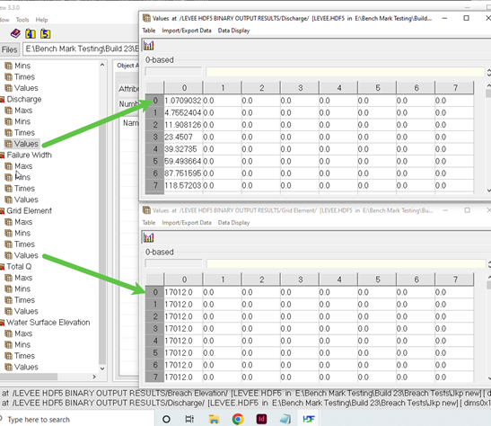
Grid element listed for the failure direction (ft or m)
Total Q sum of all Q for 10 timesteps (cfs or cms)
Water surface Elevation at the failure direction (ft or m)
To use the data in this file, join the data tables by grid number and direction and then by time because multiple grid elements and directions are reported for each output interval.
LEVEE.OUT
The LEVEE.OUT file contains a list of the grid elements with a levee that failed. Failure width, failure elevation, discharge from the levee breach and the time of failure occurrence are listed. The file shows failure expansion into multiple directions and adjacent levee elements. The total breach is written to ge#_PRESCRIBED_BREACH.OUT. This file also reports the time at which the breach reaches the bottom of the grid elevation and the flow for that direction changes from weir flow to overland flow.
Grid element
Direction - fail direction 1-8
Water surface elevation (ft or m)
Breach elevation (ft or m)
Failure width (ft or m)
Discharge for cutoff direction (cfs or cms)
Avg Q for 10 timesteps (cfs or cms)
Time (hrs)
LEVEEDEFIC.OUT
The levee freeboard deficit is listed in this file. Five levels of freeboard deficit are reported:
0 = freeboard > 3 ft (0.9 m)
1 = 2 ft (0.6 m) < freeboard < 3 ft (0.9 m)
2 = 1 ft (0.3 m) < freeboard < 2 ft (0.6 m)
3 = freeboard < 1 ft (0.3 m)
4 = levee is overtopped by flow.
Grid element
Xcoord
Ycoord
Levee deficit
GE_LEVFAIL.OUT
This file reports the levee failure expansion for a single grid element where the breach starts. Do not use this file to try and understand the total failure because it is confined to a single grid element. Use LEVEE.OUT to review prescribed breach expansion. LEVEE.HDF5 also reports levee expansion for prescribed breach.
This file reports:
Grid element
Direction - fail direction 1-8
Water surface elevation (ft or m)
Breach elevation (ft or m)
Failure width (ft or m) limited to one grid element
Discharge for cutoff direction (cfs or cms)
Avg Q for 10 timesteps (cfs or cms)
Time (hrs)
GE_PRESCRIBED_BREACH Q.OUT
This file reports the breach discharge hydrograph in cubic feet per second or cubic meters per second through a dam or levee that was assigned prescribed breach. The grid element number indications the location where the breach initiated. The discharge is total flow through all expansion elements.
Time (hrs)
Discharge (cfs or cms)
LEVOVERTOP.OUT
The discharge hydrograph overtopping the levee within the grid element is reported in this file. Only those levee grid elements with a negative levee element number in LEVEE.DAT will be reported when overtopped. The discharge is combined for all the potential levee overtopping directions for the grid element. The rows of data are grouped by Grid element. There is a row break when the Peak Q and Time are reported.
Discharge total
Time - time of overtopping,
Discharge direction columns N, E, S, W, NE, SE, SW, NW. Negative value means flow is moving from the opposite grid to the grid with the levee assigned.
LEVOVERTOPMAX.OUT
The max discharge of the water overtopping the levee within the grid element is reported in this file. Only those levee grid elements with a negative levee element number in LEVEE.DAT will be reported when overtopped. The discharge is combined for all the potential levee overtopping directions for the grid element.
Grid element
Discharge max (cfs or cms)
Time of overtop minus overtop time (hrs)
LOW_LEVEE_CREST_ELEVATIONS.OUT
Levee crest elevations that are less than a minimum difference above the ground are list in this file. The minimum elevation difference is the DEPRESSDEPTH parameter in the CONT.DAT file. This variable is used to evaluate the minimum difference in the levee crest elevations compared to the ground elevation on both sides of the levee. If used with DEPRESSED_ELEMENTS.OUT, the DEPRESSDEPTH variable either has to be the same value or two separate independent simulations are required for different values (use SIMUL = 0.1 or 0.01 hrs for each).
Grid element - element with the levee assigned
Neighbor grid element - element across from the levee cutoff direction
Direction - levee cutoff direction 1-8
Levee crest elevation (ft or m)
Ground elevation (ft or m)
Elevation difference (ft or m)
MANNINGS_N.RGH
MANNINGS_N.RGH is a duplicate file of the MANNINGS_N.DAT file with the updated Manning’s n-value changes that were reported in the ROUGH.OUT file. The maximum and final Manning’s n-value changes are listed in the ROUGH.OUT.
MAXQBYDIR.OUT
This output file lists the maximum floodplain grid element discharge according to the eight flow directions and the time of occurrence.
Grid element
North - Qmax (cfs or cms) Time
NE - Qmax (cfs or cms) Time
East - Qmax (cfs or cms) Time
SE - Qmax (cfs or cms) Time
South - Qmax (cfs or cms) Time
SW - Qmax (cfs or cms) Time
West - Qmax (cfs or cms) Time
NW - Qmax (cfs or cms) Time
MAXQHYD.OUT
This output file lists the maximum floodplain grid element discharge and the associated hydraulics including:
Grid element
Time
Maximum discharge (cfs or cms)
Direction - direction max discharge was recorded 1-8
Water surface
Depth (ft or m)
Velocity (fps or mps)
Combined Qmax (cfs or cms)
Direction - direction max velocity 1-8
MAXQRESOLVED.OUT
The maximum discharge resolved by flow direction listed for all eight flow directions regardless of the time of occurrence are reported to this file. The resolved flow direction maximum discharge includes the sum of the primary flow direction and the two diagonal flow directions.
Grid element
North - Qmax (cfs or cms)
Northeast - Qmax (cfs or cms)
East - Qmax (cfs or cms)
Southeast - Qmax (cfs or cms)
South - Qmax (cfs or cms)
Southwest - Qmax (cfs or cms)
West - Qmax (cfs or cms)
Northwest - Qmax (cfs or cms)
MAXWSELEV.OUT
Similar to DEPTH.OUT, this file contains grid element number, x-coordinate, y-coordinate, and the maximum water surface elevation of either the floodplain or channel.
Grid element
Xcoord
Ycoord
Water surface elevation (ft or m)
MODFLOW CHANNEL INFILTRATION TOTALS.OUT
Total accumulated volume of water that infiltrates from the CH to MODFLOW at each MODFLOW timestep.
Time
Accumulated infiltration volume CH (ft3 or m3)
MODFLOW CHANNEL INFILTRATION VOLUMES.OUT
Accumulated volume of water that infiltrates from CH to MODFLOW at each Modflow timestep and for each cell.
Time
Grid element
Accumulated infiltration volume CH (ft3 or m3)
MODFLOW FP INFILTRATION TOTALS.OUT
Total accumulated volume of water that infiltrates from the FP to MODFLOW at each MODFLOW timestep.
Time
Accumulated infiltration volume FP (ft3 or m3)
MODFLOW FP INFILTRATION VOLUMES.OUT
Accumulated volume of water that infiltrates from FP to MODFLOW at each Modflow timestep and for each cell.
Time
Grid element
Accumulated infiltration volume FP (ft3 or m3)
MULTCHN.OUT
The multiple channel routine routes the overland flow between grid elements as concentrated channel flow (i.e. rill and gully flow). For grid elements specified for multiple channel flow, overland flow only occurs within the grid element and the flow between the elements is conveyed as gully flow. Once the flow enters the multiple channels, the channel will enlarge to contain the flow. This occurs when the flow depth exceeds the specified channel depth. The channel increases by a specified incremental width. After the peak discharge has passed and the flow depth is less than one foot, the channel width will decrease until it reaches the original width. MULTCHN.OUT identifies multiple channel revisions including the maximum width, final width and the original width for each grid element. The file has the following format:
Grid element
Max width (ft or m)
Depth (ft or m)
Qmax (cfs or cms)
WSEL= Water Surface Elevation for each cell.
MULTSTEEP.OUT
This file lists the number of steep multiple channels found within the assigned minimum and maximum slopes.
MULT.RGH
MULT.RGH is a duplicate file of the MULT.DAT file with the updated Manning’s n-value changes that were reported in the ROUGH.OUT file. The maximum and final Manning’s n-value changes are listed in the ROUGH.OUT.
OUTNQ.OUT
The OUTNQ.OUT file is separated into two data areas. The first section contains a summary of the maximum discharge, time of peak and the discharge hydrograph for each floodplain outflow element. The second section is column data that includes the following for each outflow node:
Grid element
Time (hrs)
Discharge (cfs or cms)
OVERBANK.OUT
When the flow exceeds bankfull discharge and begins to inundate the floodplain, the channel grid element and time of overbank flood occurrence are written to this file.
Grid element
Xcoord
Ycoord
Time
Water surface elevation - elevation at time water goes overbank (ft or m)
Thalweg depth - depth at time water goes overbank (ft or m)
Velocity - average velocity at time water goes overbank (fps or mps)
Discharge - q at time water goes overbank (cfs or cms)
Overbank volume
Available floodplain area
RAINCELL.CHK
This file was created for the user to be able check the magnitude of the average total rainfall for all grids and the total rainfall for each grid during the simulation, the file contains the following:
Line 1 Average grid element rainfall for the entire storm=, RGRIDTOTALAVE
Line 2 1 to NNOD TOTAL RAINFALL
RAINONECELL.CHK
This is an internal file that I use for troubleshooting. We need to make sure the unit is marked as used in the unit file list. We eventually might want to let the user have access to this file.
REVISED_RATING_TABLE.OUT
This file reports suggested revisions to hydraulic structure rating tables based on the inflow discharge to the hydraulic structure inlet floodplain or channel element. These revisions are usually the result of the rating table being created with low n-values or because the rating table has insufficient low depth stage-discharge pairs or the cross-section do not match the rating table data.
ROUGH.OUT
The ROUGH.OUT file reports the automated Manning’s n-value adjustment during model simulation including n-value change for exceeding the Courant number and exceeding the limiting Froude. The user specifies a maximum Froude number for overland, channel and street flow. When the computed Froude number exceeds the defined maximum value for a given grid element, the n-value for that grid element is increased by a value based on the percent change in the n-value. During the falling limb of the hydrograph when the Froude number is no longer exceeded, the n-value is decreased by 0.0005 until the original n-value is reached. When the Courant number timestep is exceeded consecutive times by the same grid element, then n-value is also increased. With increasing consecutive timestep decrements, the increase in n-value decreases. The maximum n-value, time of occurrence, and original n-values for floodplain, channel and street are listed in ROUGH.OUT by grid element.
SD MANHOLEPOPUP.OUT
SDManholePopUp.OUT is created when at least one manhole pops in the storm drain system. This file contains the following information:
Xcoord
Ycoord
Grid element
Manhole ID
Time
Pressure Head
Rim elevation + Surcharge Elevation
FLO-2D WSE.
SEDCHAN.OUT
The sediment transport routine will compute scour and deposition in the channel.
Grid element
Xcoord
Ycoord
Maximum deposition (ft or m)
Maximum scour (ft or m)
Final bed elevation difference (ft or m)
Maximum water surface elevation (ft or m)
SEDCONSERV.OUT
The sediment transport conservation summary is listed by output interval.
Time
Inflow (cuft or cum)
Floodplain storage (cuft or cum)
Channel storage (cuft or cum)
Street storage (cuft or cum)
Outflow (cuft or cum)
Conservation total (cuft or cum)
Conservation percent (cuft or cum)
SEDFP.OUT
Similar to the SEDCHAN.OUT file, the floodplain scour and deposition are reported in the SEDFP.OUT file.
Grid element
Xcoord
Ycoord
Maximum deposition (ft or m)
Maximum scour (ft or m)
Final bed elevation difference (ft or m)
Maximum water surface elevation (ft or m)
SEDTRAN.OUT
The sediment transport capacity (cfs or cms) computations for each of the eleven sediment transport equations are listed by output interval in this file for a single specified grid element. Set the variable to print the file in the SED.DAT file or with the FLO-2D Plugin.
Zeller/Fullerton
Yang
Englund/Hansen
Ackers/White
Laursen
Toffaleti
MPM-Woo
MPM-Smart
Karim/Kennedy
Parker/Klingemen/McClean
Van Rijn
SPECENERGY.OUT
The specific energy is the sum of the depth plus the velocity head. This file lists the maximum specific energy (ft or m) for a floodplain grid element and includes grid element number, grid element x- and y-coordinates and maximum specific energy.
Grid element
Xcoord
Ycoord
Specific energy (ft or m)
STATICPRESS.OUT
The spatially variable static force per linear foot for each floodplain element is presented is this file by grid element number, x- and y-coordinates and force per linear foot or meter.
Grid element
Xcoord
Ycoord
Static pressure (lb/ft or N/m)
STEEPROUGH.OUT
This file lists the final changes to Manning’s n-values for the grid elements with steep slopes.
Grid element
Receiving grid element
Original n-value
Max n-value
STORMDRAIN_ERROR.CHK
Storm drain error and warning messages are written to this file. The error/warnings related to conflicts between storm drain features and surface components as well as the elevations checks are listed. The Storm Drain Guidelines manual has a troubleshooting section that will help determine how the errors and conflicts can be corrected.
STREET.RGH
This file lists the final changes to Manning’s n-values for the street grid elements. The maximum and final Manning’s n-values are reported in the ROUGH.OUT file. If the n-value changes are acceptable, STREET.RGH can be renamed to STREET.DAT for the next FLO-2D flood simulation. This automates the spatial adjustment of n-values for street elements that exceeded the limiting Froude number.
STREET.OUT
Similar to DEPTH.OUT, this file contains the street element x- and y- coordinates and the maximum street flow depth.
Grid element
Xcoord
Ycoord
Maximum street depth (ft or m)
STRELEV.OUT
Final street elevations used in the model simulation are listed in this file.
Grid element
Final street elevation (ft or m)
SUMMARY.OUT
This file lists the volume conservation summary table including the simulation output time interval, the minimum timestep and flood volume conservation. It also reports the inflow hydrograph, rainfall, infiltration loss, and outflow and storage volumes. Review the volume conservation accuracy and the final distribution of volume in this file.
Mass balance information for the various flow components is reported.
Inflows
Inflow hydrograph volume
Rainfall volume
Storage
Floodplain storage
Channel storage
TOL storage (see TOLER.DAT)
Outflow
Infiltration and interception
Floodplain outflow
Channel infiltration
Storm drain exchange volume is reported
Storm drain inflow
Total inflow
Total outflow
Storm drain return flow
Storm drain mass balance Storm drain volume data from swmm.rpt
Wet weather inflow
External inflow
External outflow
Return flow to surface
Total storm drain storage
Continuity error Totals are reported
Total outflow
Total volume and storage
Area of inundation data
Wetted floodplain area
Wetted channel area Project Specific Data
Grid element siz
Total number of grid elements
Grid System area (acres or m2 and mi2 or km2) Average hydraulics
Discharge (cfs or cms)
Velocity (fps or cms)
Flow area (ft2 or m2)
Flow depth (ft or m)
Flow width (ft or m) Computation data
Total Computations
Computer run time (hrs)
Termination date and time
SUPER.OUT
Instead of writing the supercritical flow messages at runtime (and limiting them to the first 100 or so instances), the maximum supercritical Froude number (associated depth and time and number of occurrences) are tracked and sorted by Froude number in descending order at model termination for both floodplain and channel (at the bottom of the file). It also indicates if the grid elements are hydraulic structures. By correlating this file with TIME.OUT, ROUGH.OUT, VELTIMEFP.OUT, the user can address the problematic elements with greater insight.
Grid element
Max Froude number
Depth (ft or m)
Time
Number of supercritical timesteps
SURFAREA.OUT
The SURFAREA.OUT lists the available flow surface area in each grid element. The area reduction factors (ARF) remove a portion of the surface area of a grid element to account for buildings or other features that occupy the flow surface area. Channels, streets and multiple channels also require a portion of the floodplain surface. The remaining floodplain surface area is reported. At the end of the file, the maximum area of floodplain inundation (including the channel surface area) for the entire grid system is listed by output time interval. This can be an informative data file for the user. The SURFAREA.OUT file enables a review of the surface area distribution between the various components.
Grid element
Arf-reduced area - total area minus the building
Channel area - bank elements covered by part of the channel
Street area - area covered by street component
Mult channel area - area covered by mult channel
Overland area - remaining area not covered by a component
Mult channels - switch tells the user this element has a mult channel.
SWMM.OUT
This is the binary file that contains the numerical results from a storm drain simulation. View it with the storm drain interface (GUI) to create the time series plots and tables, profile plots, and statistical analyses. For more information, look at: C:\Users\Public\Documents\FLO-2D PRO Documentation\flo_help\Manuals\FLO-2D Storm Drain Manual.pdf.
SWMM.RPT
This file contains the report information and the results of the storm drain flood routing in ASCII Format. The storm drain model engine generates this file. It is extensive and contains discharge hydrographs for every drain inlet, outlet and conduit. The Storm Drain Guidelines manual is the best resource for developing, troubleshooting and reviewing anything storm drain related. For more information look at: C:\Users\Public\Documents\ FLO-2D PRO Documentation\flo_help\Manuals\FLO-2D Storm Drain Manual.pdf.
SWMMOUTFIN.OUT
This file reports the storm drain outfall hydrographs for return flow to the surface water system. This file lists the grid element (or channel element if applicable) followed by the time and discharge pairs. The Storm Drain Guidelines manual is the best resource for developing, troubleshooting and reviewing anything storm drain related. For more information look at: C:\ Users\Public\Documents\FLO-2D PRO Documentation\flo_help\Manuals\FLO-2D Storm Drain Manual.pdf.
SWMMQIN.OUT
The discharge hydrograph and return flow (time, discharge and return flow) into each storm drain inlet of the pipe network is reported in this file. Each inlet has a discharge hydrograph and return flow reported each output interval TOUT timestep. The Storm Drain Guidelines manual is the best resource for developing, troubleshooting and reviewing anything storm drain related. For more information look at: C:\Users\Public\Documents\ FLO-2D PRO Documentation\flo_help\Manuals\FLO-2D Storm Drain Manual.pdf
SD ManholePopUp.OUT
This file reports the storm drain manhole nodes that have enough pressure head to pop off the manhole cover. The pop off pressure head is an instantaneous head that removes the manhole cover. This pressure head can be different to the reported pressure head in the SWMM.RPT file.
Manhole ID
Popped time
Pressure head pop off must be greater than the following:
Rim and surcharge head
FLO-2D water surface elevation
TIMDEP.OUT
This file contains grid element, flow depth, velocity and velocity direction x and y and water surface elevation for each floodplain grid element at the user specified time intervals (TIMTEP in CONT.DAT). This file is also required for a time-lapse simulation in the MAXPLOT and FLO-2D MapCrafter post-processor programs.
Time - output interval for time series. Single value at the top of the columns.
Grid element
Depth (ft or m)
Velocity (sqrt(x2 +y2)) (fps or mps)
Velocity x - velocity vector x
Velocity y - velocity vector y
Water surface elevation (ft or m)
TIMDEPCELL.OUT
This file contains flow depth, velocity, and velocity direction x and y, and water surface elevation for a set of grid elements defined by the TIMEDEPCELL.DAT file. The user specifies time intervals with TIMTEP in CONT.DAT.
TIMDEP.HDF5
This binary output file contains grid element, flow depth, velocity and velocity direction x and y and water surface elevation for each floodplain grid element at the user specified output time intervals (TIMTEP in CONT.DAT). This file is written in binary format (HDF5) and it has the same results as the TIMDEP.OUT file.
TIMDEP_NC4.OUT
This file contains specific details for every grid element at each time series output interval. The user specifies output time intervals with TIMTEP in CONT.DAT. This is an ASCII file.
Grid element
Depth (ft or m)
Qmax (cfs or cms)
Qmax direction - grid element direction 1 - 8
Vmax (fps or mps)
Vmax direction - grid element direction 1 - 8
Qnet - all flow in minus all flow out (cfs or cms)
Surface Exchange - switch 0 or 1 identifies if cell had any flow for the time interval
TIME.OUT
The timestep is controlled by the numerical stability criteria. When the stability criteria are exceeded for a particular grid element, the timestep is decreased. The grid elements with the highest number of timestep decreases are written to the TIME.OUT file. This file can be reviewed to determine if a specific floodplain, channel or street node is consistently causing the timestep decrease and what stability criteria is frequently being exceeded. If one grid element has caused significantly more timestep decreases than the other grid elements, then its attributes and the attributes of the contiguous grid elements should be carefully reviewed.
Grid element - floodplain, channel, or street
Number of timestep decrements
Percent change in depth
CFL Stability criteria
Dynamic wave stability criteria
The file lists the last one hundred time step decreases and the node type.
TIME_TO_ABOVE_BASEFLOW.OUT
An option to report the time to discharge above channel base flow has been implemented. The new file is generated with the following data columns.
Grid
Xcoord
Ycoord
Time to above baseflow (hrs)
This is a similar option as was coded for channel base flow. This file required that the baseflow variable IBASEFLOW is assigned with the base discharge value. This value represents the baseflow condition in a channel and the arrival time of any flow above that value is printed to this file.
TIMEONEFT.OUT
This file reports the grid element number, the x- and y-coordinates and the initial time to one foot of depth. The time to one foot of depth can be plotted in FLO-2D MapCrafter. This file is typically used for dam and levee breach analysis.
Grid element
Xcoord
Ycoord
Time to one ft depth
TIMETOPEAK.OUT
This file reports the grid element number, the x- and y-coordinates and the time of occurrence of the maximum depth. This time to maximum depth can be plotted in FLO-2D MapCrafter. While this file is typically used for dam and levee breach analysis, it valid for general flood studies.
Grid element
Xcoord
Ycoord
Time to one ft max depth
TIMETWOFT.OUT
This file reports the grid element number, the x- and y-coordinates and the initial time to two feet of depth. The time to two feet of depth can be plotted in FLO-2D MapCrafter. This file is typically used for dam and levee breach analysis.
Grid element
Xcoord
Ycoord
Time to two ft depth
TOPO_SDELEV.RGH
This file contains the elevation adjustments that were automatically corrected when the FLO-2D engine compared the floodplain grid elements to the storm drain inlet rim and type 4 invert elevations. To fully accept the changes reported to fprimelev.new, replace TOPO.DAT with this file. It is also necessary to replace the FPLAIN.DAT with FPLSIN_SDELEV.RGH.
UPS-DOWS-CONNECTIVITY.OUT
This file reports the connectivity between the upstream domain grid elements and the downstream domain grid elements.
Upstream grid element
Downstream grid elements
Velocity Output Files
These files are similar to the DEPTH.OUT file. These files contain the x- and y-coordinates and maximum velocities and can be viewed with the MAXPLOT or FLO-2D MapCrafter program.
Grid element
Xcoord
Ycoord
Velocity in the channel element (fps or mps)
The velocity output files include:
STVEL.OUT - Maximum street flow velocity;
STVELDIR.OUT - Flow direction of the maximum street flow velocity;
VELFP.OUT - Maximum floodplain flow velocity;
VELOC.OUT - Maximum channel flow velocity;
VELCHFINAL.OUT - Final channel flow velocities;
VELDIREC.OUT - Flow direction of the maximum floodplain flow velocity;
FINALVEL.OUT - Flow velocity at the end of the simulation;
FINALDIR.OUT - Flow maximum velocity direction at the end of the simulation;
VEL_X_DEPTH.OUT - The velocity x depth parameter is evaluated as a single variable. This is not max velocity x max depth, it is the maximum value of the velocity x depth that is synchronized by time.
VEL_SQUARED_X_DEPTH.OUT - The velocity squared x depth parameter is evaluated as a single variable. This is not max velocity squared x max depth, it is the maximum value of the velocity squared x depth that is synchronized by time.
The velocity output files related to two-PHASE flow include:
FINALDIR_MUD.OUT - Floodplain final mudflow velocity direction.
FINALVEL_MUD.OUT - Floodplain final mudflow velocity in the reported outflow direction.
VELDIREC_MUD.OUT - Floodplain maximum mudflow velocity direction.
VELFP_MUD.OUT - Floodplain maximum mudflow velocity in the reported outflow direction.
VELOC_MUD.OUT - Channel maximum mudflow velocity.
VELRESMAX_MUD.OUT - Floodplain maximum resolved mudflow velocity in the computed outflow direction.
VEL_X_DEPTH.OUT - The velocity x depth parameter is evaluated as a single variable (not maximum velocity times maximum depth). For two phase, the velocity x depth variable is the maximum value for the grid element for either fluid or mudflow whichever is greater.
FPWSEL_MUD.OUT - Floodplain maximum mudflow water surface elevation.
Grid or Channel Left Bank Element
Xcoord
Ycoord
Variable
VELTIMEC.OUT
This file lists the grid element number, maximum channel velocity and the time of occurrence. It is sorted from highest to lowest velocity so that an examination of the first several lines of output data will determine if there are any unreasonably high maximum channel velocities.
Grid element
Vmax in the channel element (fps or mps)
Time of occurrence
VELTIMEFP.OUT
This file lists the first 100 floodplain elements: number, maximum floodplain velocity and the time of occurrence. It is sorted from highest to lowest velocity so that an examination of the first several lines of output data will determine if there are any unreasonably high maximum floodplain velocities.
Grid element
Vmax floodplain element (fps or mps)
Depth floodplain element (ft or m)
Time of occurrence
VELRESMAX.OUT
This file lists the maximum resolved velocities as a vector field. It is not based on the 8-flow directions.
Grid element
Xcoord
Ycoord
Velresmax (fps or mps)
Velxmax
Velymax
Flow velocities are computed in 8-directions for each grid element. In the figure below, the red arrows indicate inflow to the grid element (2-directions) and the blue arrows represent outflow from the grid element (3-directions). The remaining flow directions have zero discharge and velocities. The arrow length indicates relative magnitude. If the outflow velocities from the grid element are resolved into x- and y- coordinate directions, the components would be depicted by the blue arrows in the figure below. The resultant velocity vector for the outflow from the grid element would then be represented by the green arrow.
VELTIMEST.OUT
This file lists the street element number, maximum street velocity and the time of occurrence. It is sorted from highest to lowest velocity so that an examination of the first several lines of output data will determine if there are any unreasonably high maximum street velocities.
Grid element
Vmax street element (fps or mps)
Time of occurrence
WSTIME.OUT
If the WSTIME.DAT file is created, the WSTIME.OUT file will be generated listing the channel element number, time of the measured water surface elevation, measured water surface elevation at stated time, predicted water surface elevation at stated time, difference between the water surface elevations and the cumulative difference between the measured and predicted water surfaces.
XSECAREA.OUT
When the channel cross-section option is invoked for channel routing, the channel geometry data is written to this file. It includes: grid element, flow area, top width and wetted perimeter for the lowest top of bank (bankfull flow).
Grid element
Flow area of the cross-section (sqft or sqm)
Top width of the cross-section (ft or m)
Wetted Perimeter of the cross-section (ft or m)
XSEC.OUT
This file is created by the channel sediment transport option (ISED = 1 in CONT. DAT and ISEDN = 1 for a channel segment in CHAN.DAT) for natural cross-section geometry data. It contains the final cross-section bed elevations after scour and deposition have been computed. The file looks the same as XSEC.DAT with updated elevation data.