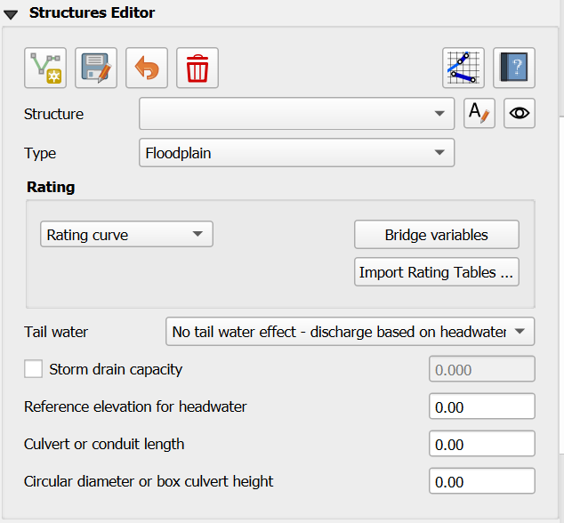
Structures Editor
The structures editor is used to set up the data for the HYSTRUCT.DAT file.
Overview
The Hydraulic Structure Editor provides a graphical user interface for defining and managing hydraulic structures within the FLO-2D Plugin. These structures control the movement of water between grid elements and are essential for simulating culverts, bridges, weirs, storm drains, and pumps in both floodplain and channel systems.
The editor supports all structure types and configurations available in FLO-2D, including:
Floodplain-to-floodplain culverts using rating curves or culvert equations
Channel-to-channel hydraulic structures with optional replacement curves
Floodplain-to-channel and channel-to-floodplain interactions
Complex bridge hydraulics using detailed coefficient tables
Pump systems and simplified storm drain configurations
Purpose
Hydraulic structures simulate the effect of physical features that convey, restrict, or redirect flow between nodes. The purpose of the editor is to simplify the process of:
Assigning node connections (inlet and outlet)
Specifying flow control methods (rating curve, culvert routine, bridge routine, etc.)
Entering reference elevations, coefficients, and geometric dimensions
Configuring optional features such as tailwater effects, structure blockage, or deck overtopping
Previewing structure behavior using visual layout and tooltip guidance
By using the editor, users can ensure structure inputs are consistent with FLO-2D model requirements and avoid common mistakes like mismatched node types or incomplete variable assignments. Each structure is validated in the UI before being saved to the HYSTRUC.DAT file, improving simulation reliability and workflow efficiency.
Note
An advanced tutorial for modeling hydraulic structures and culverts is available on the Gila Self-Help Tutorials.
Structure Editor Layout
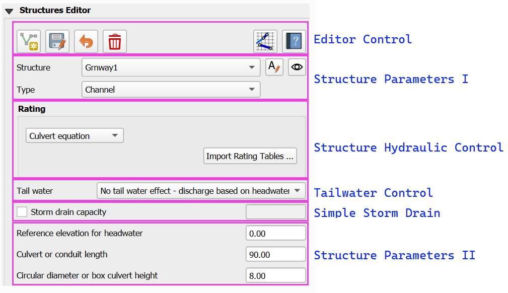
Structure Editor Control
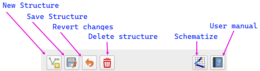
New Structure Create a new structure. Click the button to add a new polyline to connect the upstream and downstream side of a structure.
Save Structure Save the current structure and load the structure into the editor.
Revert Changes Undo any unsaved edits and revert to the last saved condition.
Delete Structure Permanently remove the selected structure from the project. Use with caution as this action cannot be undone.
Schematize Process and convert the structure into FLO-2D ready data.
User Manual Open the plugin’s user manual to view additional help documentation for hydraulic structures.
Structure Parameters I
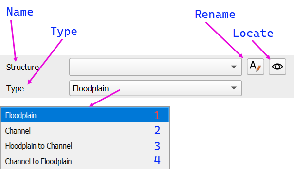
Name Enter or select the name of the structure. This identifies the outflow boundary condition in the project.
Type Choose the type of structure from the dropdown list. Options include:
Floodplain – Connect a structure between two floodplain grid elements.
Channel – Connect a structure between two left bank channel elements.
Floodplain to Channel – Connect a structure from a floodplain grid element into a left bank channel element.
Channel to Floodplain – Connect a structure from a left bank channel element to a floodplain grid element.
Note
Use the left bank channel element to connect the inlet or outlet of a structure. This is required to ensure the structure connects to the appropriate channel cross section.
Rename Use this button to rename the selected structure. The name is alpha-numeric with 30 ascii characters and no spaces.
Locate Click the locate (eye) toggle button to zoom and center the map on the selected structure.
Structure Hydraulic Control
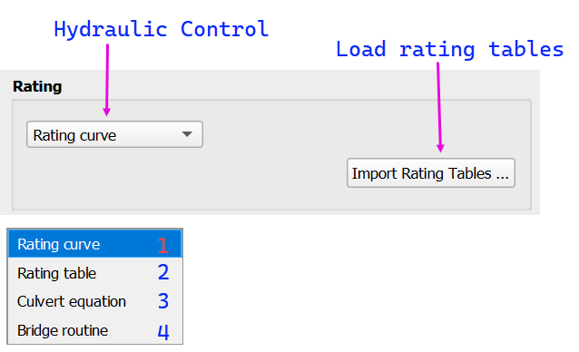
Hydraulic Control
Select the hydraulic control method that governs flow through the structure. The options correspond to different modeling approaches in FLO-2D:
Rating curve – Defines flow using a depth vs. discharge equation.
Rating table – Defines flow using a depth vs. discharge table.
Culvert equation – Uses empirical culvert equations to calculate flow based on geometry and headwater conditions.
Bridge routine – Applies a specialized bridge flow routine based on physical dimensions and flow coefficients.
Load Rating Tables
Click the Import Rating Tables button to load pre-defined rating data into the model.
Tailwater Control
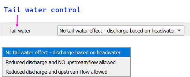
Tailwater control settings determine how downstream water levels affect culvert discharge. These options are used to simulate varying degrees of backwater influence or flow reversal at the culvert outlet:
No tail water effect – discharge based on headwater Assumes free outfall conditions. Discharge is computed solely from upstream headwater elevation. No upstream flow allowed.
Reduced discharge and NO upstream flow allowed Simulates partial submergence. Discharge is reduced based on downstream conditions, but reverse flow from outlet to inlet is not permitted. This condition is similar to a flap gate.
Reduced discharge and upstream flow allowed Allows for backflow into the upstream system under high tailwater conditions. Discharge is still reduced due to submergence.
Note
Tailwater settings simulate how downstream conditions influence flow through the structure. Use these controls when submergence or flow reversal is expected due to backwater conditions, particularly in urban or complex drainage systems.
Simple Storm Drain

Warning
Use this option sparingly. The hierarchy of flow through this system is not applied appropriately for use on more than 2 or 3 inlets.
Storm Drain Capacity
This tool provides a simplified method for linking multiple inlets to a single outlet using a maximum discharge threshold.
Only compatible with rating table structures.
Not intended to model full pipe networks. It is useful when detailed storm drain routing is unavailable or unnecessary.
The capacity value (cfs or cms) sets the maximum allowable flow. If inflow exceeds this value, excess water will pond at the inlet(s).
Structure Parameters II
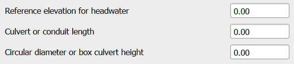
These parameters are used when defining culvert or conduit characteristics for hydraulic rating calculations:
Reference Elevation for Headwater Specifies the minimum upstream water elevation required to initiate flow through the structure. Flow will not occur until the water level reaches this elevation.
Culvert or Conduit Length
If the structure does not use a long culvert or culvert equation, enter 0.0 for length and diameter.
Culvert Equation
Defines the total length of the culvert (ft or m). Apply this length when using the culvert equation method.
Long Culvert
If the structure length exceeds 500 ft (150 m), it is considered a long culvert. In this case:
A rating table must be used.
The flow area must be defined (using ATABLE or related variables).
Long culverts simulate storage and travel time, unlike other structures that convey flow instantaneously.
Circular Diameter or Box Culvert Height
If the structure does not use a long culvert or culvert equation, enter 0.0 for both length and diameter.
Defines the internal size of the culvert (ft or m).
Culvert Equation
For circular culverts, enter the internal diameter.
For box culverts, enter the internal height.
Long Culvert
Use diameter only for flow area calculations.
Must be paired with culvert length and area table.
Only compatible with rating table structures.
Table Editor and Plot
The Table Editor and Plot section defines the rating relationships or hydraulic parameters associated with the selected structure type. Each configuration corresponds to variables in the HYSTRUC.DAT input file.
Rating Curve Table Editor
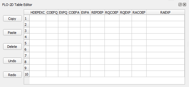
The Rating Curve Table Editor is used to define the structure’s flow behavior using headwater-dependent equations. Each column corresponds to a variable in the HYSTRUC.DAT file. These parameters are described in detail in the Data Input Manual and are used in combinations based on the selected structure type.
Variable |
Description |
|---|---|
HDEPEXC |
Maximum headwater depth valid for the rating curve. |
COEFQ, EXPQ |
Discharge equation: Q = COEFQ * depth^EXPQ |
COEFA, EXPA |
Area equation for long culverts: A = COEFA * depth^EXPA |
REPDEP |
Depth at which to switch to a replacement curve. |
RQCOEF, RQEXP |
Discharge equation for replacement curve. |
RACOEF, RAEXP |
Area equation for replacement curve (long culverts only). |
See the HYSTRUC.DAT section of the Data Input Manual for complete parameter descriptions and valid input ranges.
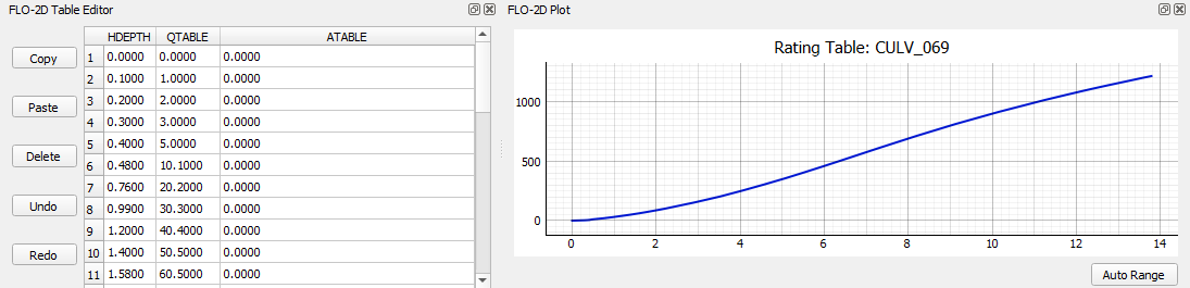
Rating Table

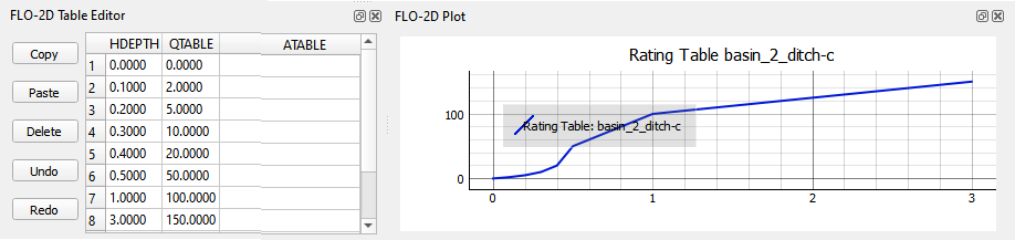
The rating table method defines flow through the structure using headwater depth (HDEPTH) and corresponding discharge (QTABLE). FLO-2D applies linear interpolation between rows to estimate the flow rate for any given depth during the simulation.
HDEPTH – Headwater depth above the structure reference elevation (ft or m).
QTABLE – Discharge value associated with each headwater depth (cfs or cms).
ATABLE – (Optional) Cross-sectional flow area vs depth (ft2 or m2) used in volume routing for long culverts. Enter 0.0 if not applicable.
The adjacent plot updates automatically and displays the rating curve graphically as depth vs. discharge. Ensure the first entry begins with HDEPTH = 0.0 and QTABLE = 0.0 to allow proper interpolation between the first two rows.
Tip
This method is commonly used for culverts, weirs, and other structures where detailed hydraulic calculations have already been performed externally or measured in the field.
Culvert Equation
The culvert equation method computes flow using geometric and frictional parameters defined by the U.S. Department of Transportation equations. This table allows input of the following:
TYPEC – Culvert shape: 1 = box, 2 = pipe
TYPEEN – Entrance configuration (1–3 based on shape)
CULVERTN – Manning’s n-value for internal culvert roughness
KE – Entrance loss coefficient
CUBASE – Width of the box culvert or set to 0 for circular culverts
MULTBARRELS – Number of identical culvert barrels or cells
These parameters are used to estimate flow under both inlet and outlet control conditions. For additional guidance on selecting values and entrance types, refer to the Culvert Equation Data section.
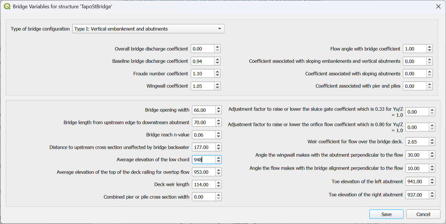
Bridge Routine
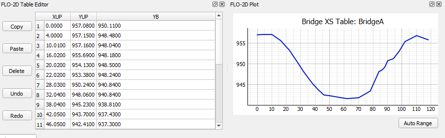
The bridge routine provides a detailed method for modeling flow through bridge openings using upstream and downstream cross sections and coefficient-based flow equations derived from U.S. Geological Survey (USGS) research.
This configuration allows input of:
This table defines the upstream and downstream cross sections used in the bridge routine. Cross section geometry is entered as station-elevation points along the bridge profile:
XUP – Station of each cross section point.
YUP – Elevation of the corresponding upstream cross section.
YB – Elevation of the corresponding downstream point at the same station.
Note
For a complete example showing how to use this table along with the bridge coefficients and geometry fields, refer to the Bridge Example in the Examples section.
Culvert Equation Data
Culvert equations define flow through a culvert based on geometric and hydraulic properties. This information is entered in the Structures Editor and the FLO-2D Table Editor, as shown below.
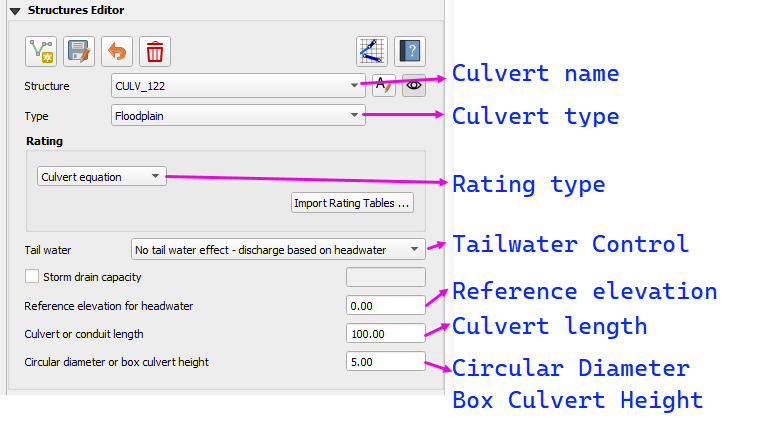
Structures Editor Fields
The following fields are available in the Structures Editor:
Structure – Name of the culvert structure (e.g., CULV_122)
Type – Designation of the culvert as Floodplain or Channel
Rating – Select Culvert Equation or import from a rating table
Tailwater Control – Choose how downstream water levels are handled
Reference Elevation – Elevation for the inlet headwater (ft)
Culvert Length – Total length of the culvert barrel (ft)
Culvert Diameter or Box Height – Inside diameter for pipes or height for box culverts (ft)
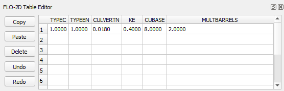
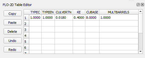
Culvert Geometry Table
The FLO-2D Table Editor stores additional culvert equation variables:
TYPEC |
TYPEEN |
CULVERTN |
KE |
CUBASE |
MULTBARRELS |
|---|---|---|---|---|---|
1.0 |
1.0 |
0.0180 |
0.4 |
8.0 |
1.0 |
Field Descriptions:
TYPEC – Culvert shape: 1 = box, 2 = pipe
TYPEEN – Entrance type (see below)
CULVERTN – Manning’s n value for the culvert
KE – Entrance loss coefficient
CUBASE – Culvert width (for box) or diameter (for pipe)
MULTBARRELS – Number of barrels (1.0 for single-barrel)
Culvert Type Switch
The culvert shape is defined using the TYPEC(I) variable:
1= Box culvert2= Pipe culvert
Note
Box culverts are defined by height and width. Pipe culverts are defined by circular diameter.
Entrance Type Codes
Box Entrance Types (TYPEEN)
1– Wingwall flare 30° to 75°2– Wingwall flare 90° or 15°3– Wingwall flare 0°
Pipe Entrance Types (TYPEEN)
1– Square edge with headwall2– Socket end with headwall3– Socket end projecting
Entrance Loss Coefficients
The entrance head loss is calculated using the following equation:
- Where:
H_eis entrance head loss (ft or m)K_eis the entrance loss coefficientvis velocity in the culvert barrel (ft/s or m/s)gis gravitational acceleration (32.2 ft/s² or 9.81 m/s²)
Entrance Loss Coefficient Table (HDS-5)
Pipe, Concrete
Type of Structure and Design of Entrance |
Ke |
|---|---|
Projecting from fill, socket end (groove-end) |
0.2 |
Projecting from fill, square cut end |
0.5 |
Headwall or headwall and wingwalls |
0.2 |
Socket end of pipe (groove-end) |
0.2 |
Square-edge |
0.5 |
Rounded (radius = D/12) |
0.2 |
Mitered to conform to fill slope |
0.7 |
End-section conforming to fill slope |
0.5 |
Beveled edges, 33.7° or 45° bevels |
0.2 |
Side- or slope-tapered inlet |
0.2 |
Note
These values are based on the Hydraulic Design of Highway Culverts – HDS-5 – Third Edition and used in inlet control flow calculations.
Bridge Data
Bridge parameters can be defined for a structure.
The USGS bridge tables are used to define the flow though a bridge with bridge geometry and discharge coefficients.
Note
See Bridge tutorial and Bridge guidelines for a detailed guide.
Example Hydraulic Structures
Note
These examples show the final configuration only. For step by step instructions see the Self Help Tutorials
Floodplain to Floodplain Structure
Floodplain to Floodplain
Rating Table
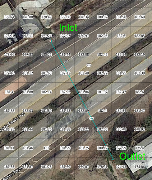
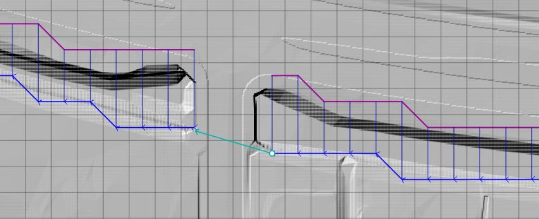
This example will model a culvert system between two floodplain nodes.
The floodplain structure uses the grid element elevation as it’s inlet and outlet invert elevations. In this case the inlet invert is 177.24 ft and the outlet invert is 174.13 ft.
Note
Because culverts have a headwall, the grid elevation may need an adjustment down to the invert. The advanced culvert tutorial in the Self Help Kit shows how to make that elevation correction. Self Help Tutorials
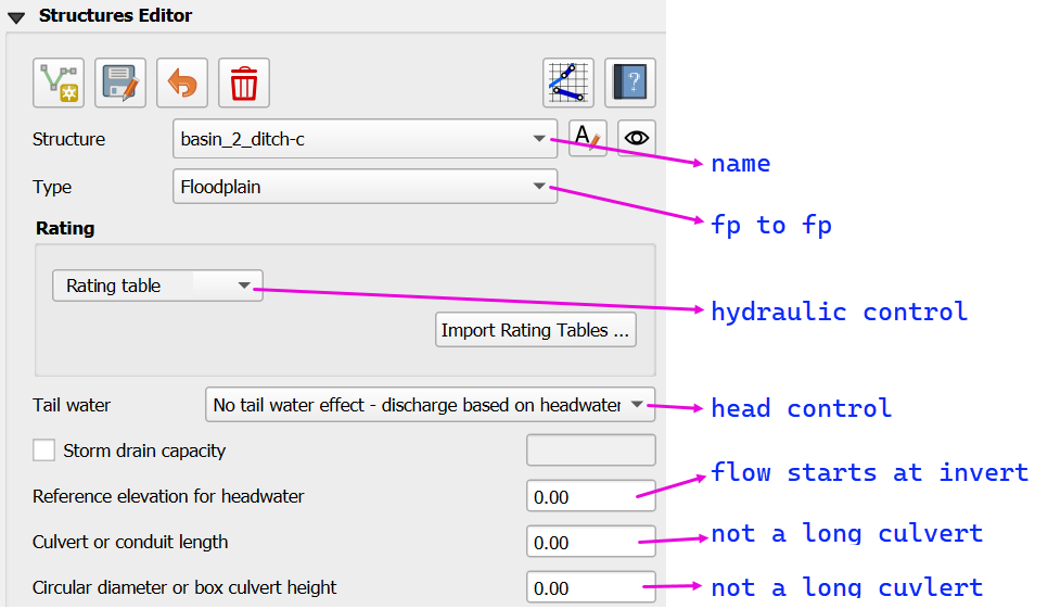
This structure is a floodplain to floodplain culvert that uses a rating table.
It has a headwater control so the Tailwater switch is set to “0” or No tailwater effect.
It does not have a reference elevation for headwater so the flow starts at the invert elevation.
It’s not considered a long culvert so the length and diameter are both “0.00”.
The rating table is a headwater control rating table.
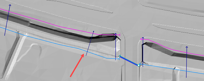
Channel to Channel Structure
Channel to Channel
Generalized Culvert Equation
This structure will simulate discharge through a box culvert. This example has a box culvert that is longer than the grid element. The channel segments are split up to allow for the width of the roadway.
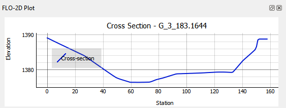
When setting up a channel with a culvert, it is important to set the cross sections so they can represent the expansion and contraction of the channel leading up to and away from the channel.
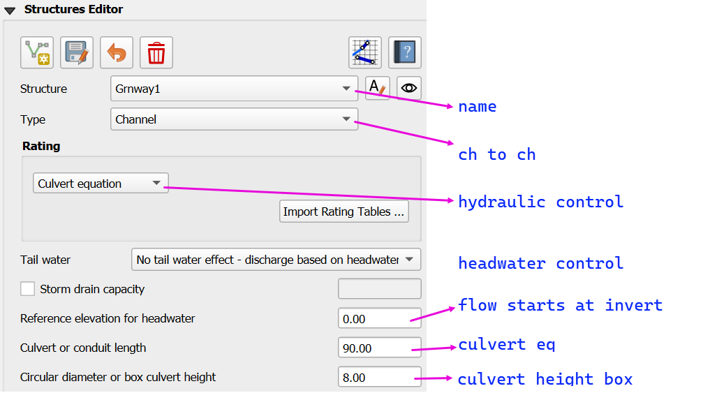
This structure is a channel to channel culvert that uses a culvert equation.
It has a headwater control so the Tailwater switch is set to “0” or No tailwater effect.
It does not have a reference elevation for headwater so the flow starts at the upstream channel invert elevation.
It is a culvert equation so the culvert length is 90 ft and the box height is 8 ft.
The remaining culvert parameters are defined in the Table Editor.
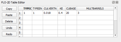
TYPEC = 1 (box)
TYPEEN = 1 (wingwall flare)
CULVERTN = 0.018
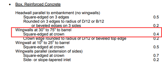
KE 0.4 (wingwall and square edge)
CUBASE = 20 ft (width)
MULTBARRELS = 3 (multi-barrel)
Culvert Type Switch
The culvert shape is defined using the TYPEC(I) variable:
1= Box culvert2= Pipe culvert
Box Entrance Types (TYPEEN)
1– Wingwall flare 30° to 75°2– Wingwall flare 90° or 15°3– Wingwall flare 0°
Box Losses
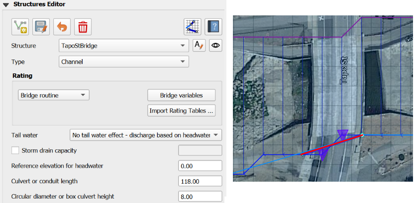
Floodplain to Channel Structure
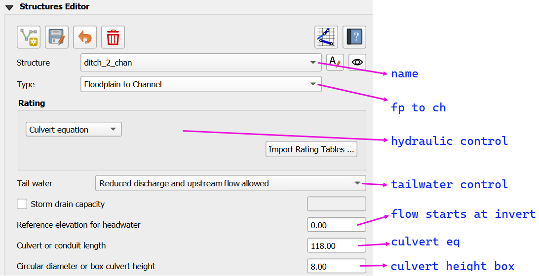
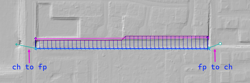
Floodplain to Channel
Culvert equation
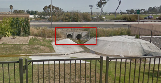
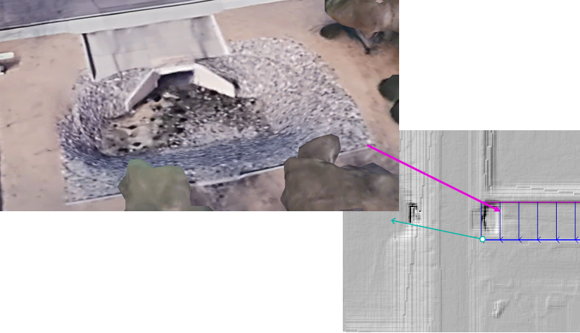
This example shows a culvert that connects a basin to a channel laterally.
Important
The structure always connects to left bank of a channel regardless of which bank the structure is positioned on. This is because the structure connects to the cross section and the reference point is always the left bank grid element number.
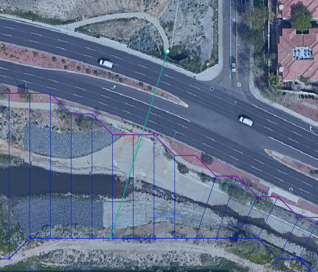
The culvert is assigned to the channel cross section.
That is why the feature must be applied to a left bank channel node.
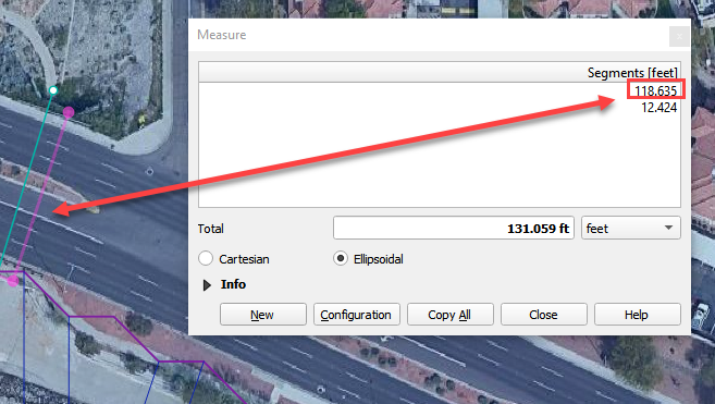
The culvert length is 118ft.
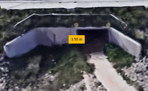
This is a pedestrian crossing so the culvert height must be at least 8 ft.
The width of the structure is approximately 12 ft.
There are 30-degree wingwalls.
The stage of the water in the channel will result in a tailwater control.
The tailwater switch should be set to Reduced Discharge and upstream flow allowed.
The remaining culvert parameters are defined in the Table Editor.
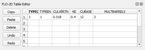
TYPEC = 1 (box)
TYPEEN = 1 (wingwall flare)
CULVERTN = 0.018
KE 0.4 (wingwall and square edge)
CUBASE = 12 ft (width)
MULTBARRELS = 1 (single-barrel)
Culvert Type Switch
The culvert shape is defined using the TYPEC(I) variable:
1= Box culvert2= Pipe culvert
Box Entrance Types (TYPEEN)
1– Wingwall flare 30° to 75°2– Wingwall flare 90° or 15°3– Wingwall flare 0°
Box Losses
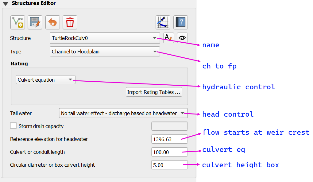
Channel to Floodplain Structure
Channel to Floodplain
Culvert equation
This example has a channel to floodplain box culvert on the downstream side. The example will not outline the the floodplain to channel circular culvert on the upstream side.
The channel to floodplain culvert is a box culvert with a sedimentation weir on the upstream side.
This structure is a channel to floodplain culvert that uses a culvert equation.
It has a headwater control so the tailwater switch is set to “0” or No tailwater effect.
It has a sedimentation weir so the reference elevation for headwater is 1396.63.
It needs a culvert length 100.00 ft and a culvert height 5.00 ft because it uses the culvert equation.
The remaining culvert parameters are defined in the Table Editor.
TYPEC = 1 (box)
TYPEEN = 1 (wingwall flare)
CULVERTN = 0.018
KE 0.4 (wingwall and square edge)
CUBASE = 8 ft (width)
MULTBARRELS = 1 (single-barrel)
Culvert Type Switch
The culvert shape is defined using the TYPEC(I) variable:
1= Box culvert2= Pipe culvert
Box Entrance Types (TYPEEN)
1– Wingwall flare 30° to 75°2– Wingwall flare 90° or 15°3– Wingwall flare 0°
Box Losses