Hydraulic Structures - Culverts
Set up culverts using Rating Tables and Culvert Equations using QGIS and the FLO-2D Plugin.
Note
It will be easier to view these videos on YouTube.
Set the video playback speed to 2x to complete the lessons faster.
The videos are more detailed whereas the text gives the minimum steps needed to complete the project.
Import and Review Culvert Data
This video gives a review of the hydraulic structures lesson. Follow the steps below to complete the lesson.
Set-up Culvert Structures
This part of the lesson shows how to import and configure hydraulic structures in your FLO-2D project using QGIS.
Note
Covert (culvert) data rarely comes as pre-formatted GIS line features. Most often, site surveys or as-built drawings are needed.
Step 1: Import the Hydraulic Structure Template
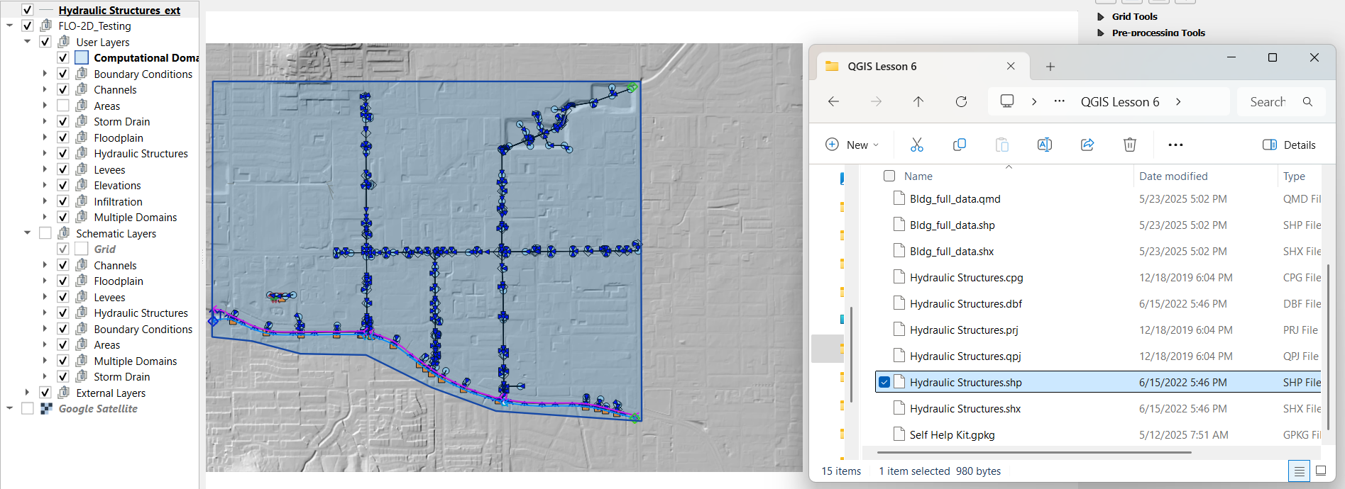
Open QGIS Lesson 6 project.
Drag and drop the
hydraulic_structures.shpfile from the lesson data folder onto the map.
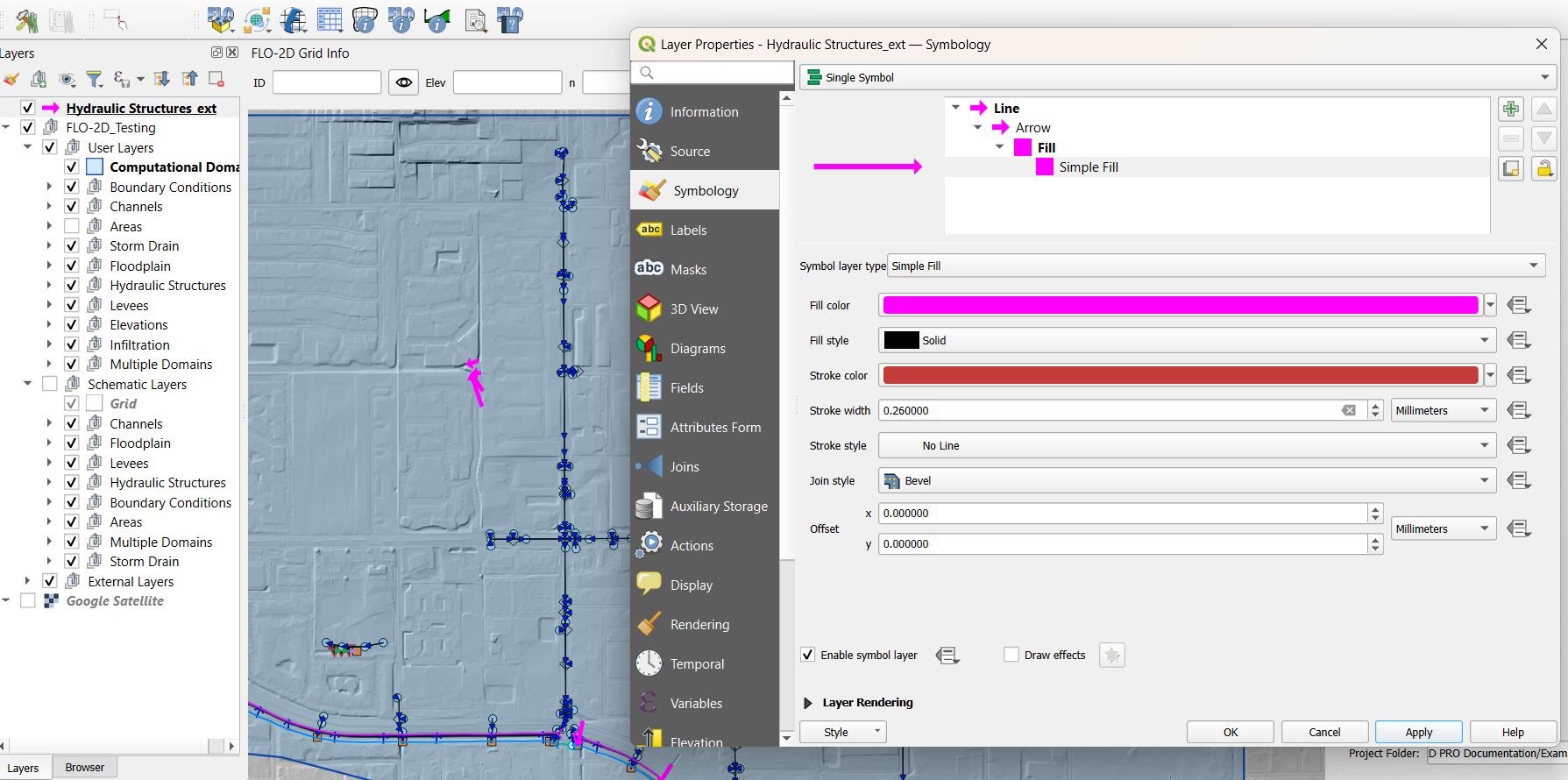
Change symbology:
Set to Arrow symbol to show flow direction.
Optionally brighten the line color.
Tip
The arrowhead marks the Outlet, and the first vertex is the Inlet.
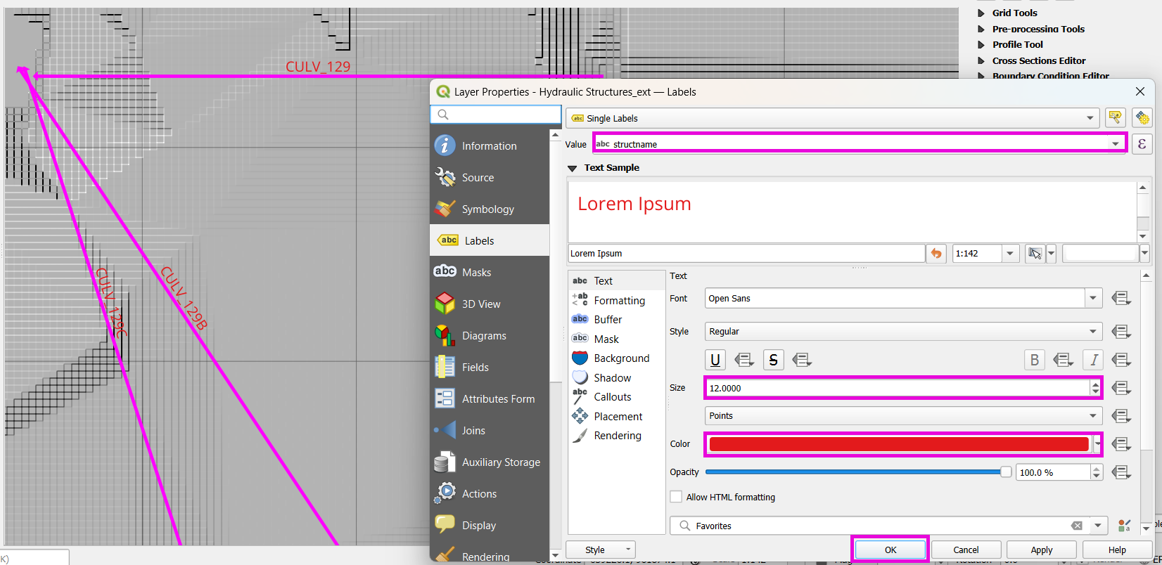
Label hydraulic structures:
Open layer properties and go to Labels.
Choose the field structname to display.
Adjust font size and color for better visibility.
Step 2: Copy from Template Layer
Select features from the template layer:
Use Select All Features tool or
Ctrl + A.Copy with
Ctrl + C.
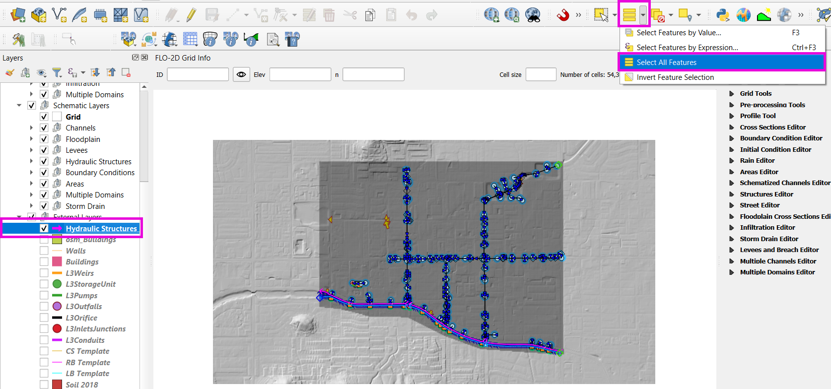
Activate the Structure layer from the FLO-2D widget editor:
Ensure editing mode is on.
Paste with
Ctrl + V.
Save the edits.
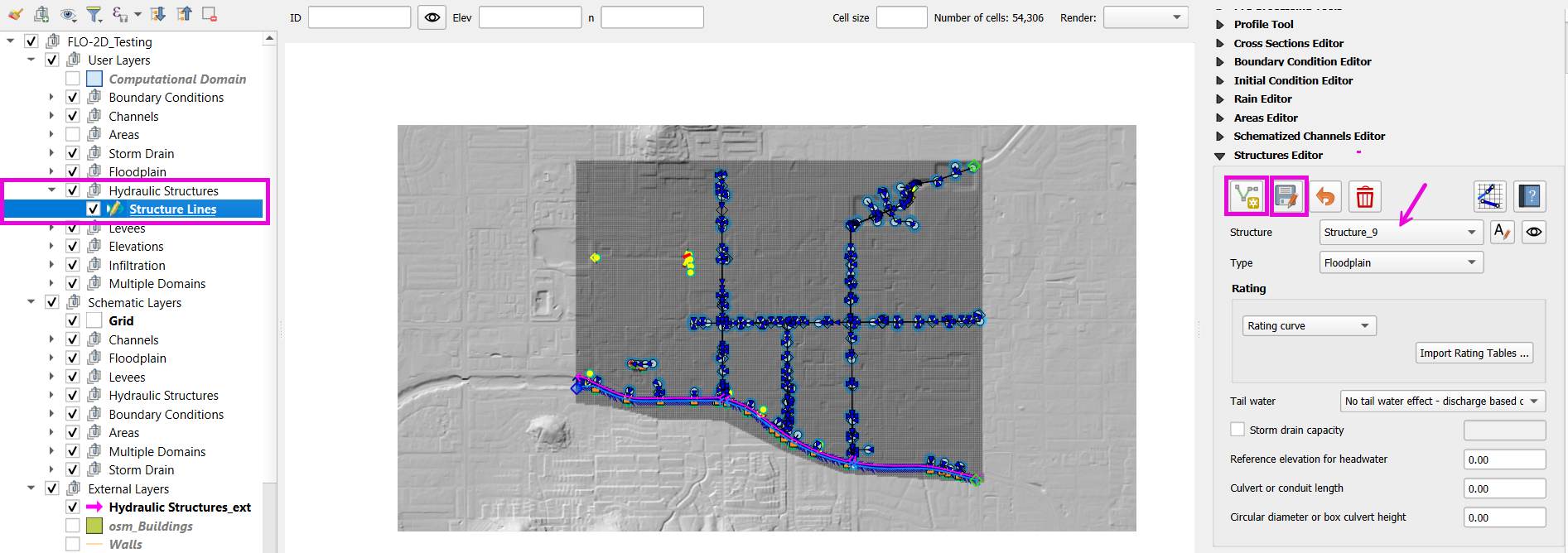
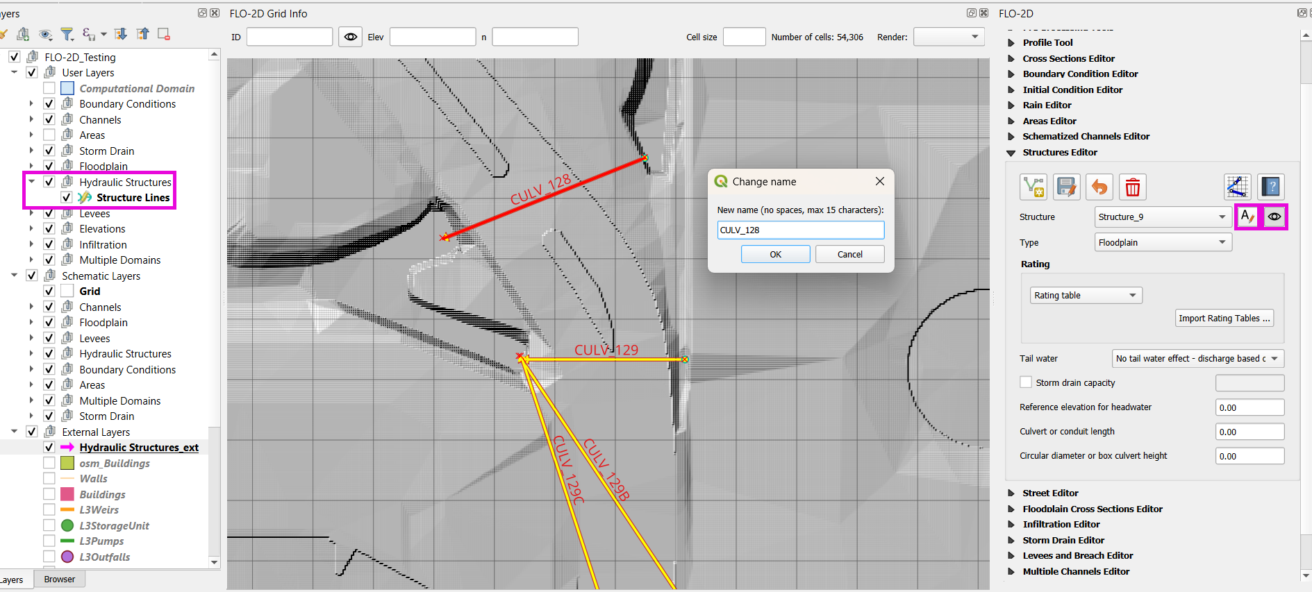
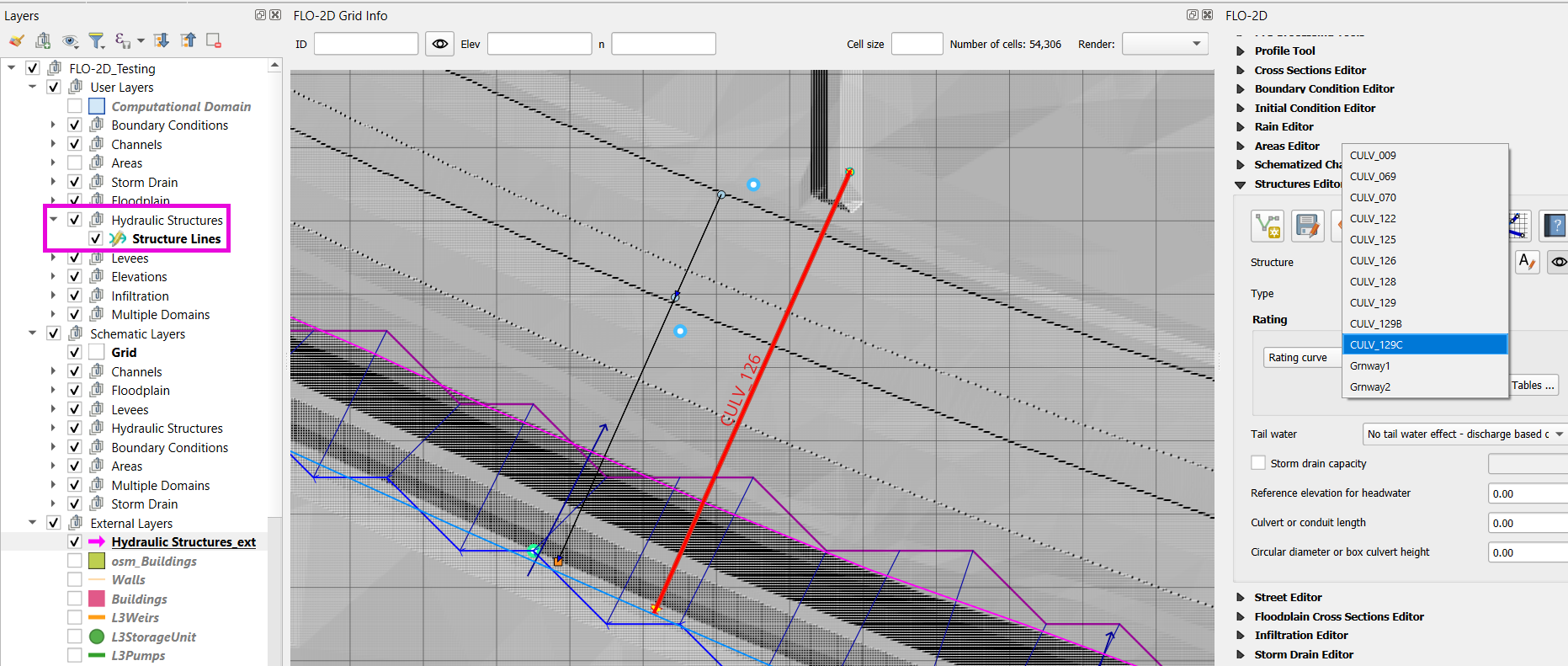
Step 3: Name and Review Each Structure
Use the Center on structure button to step through.
Rename each one based on the provided naming convention (
CULV_*).Set labels to
structnamefield with 12pt font for visibility.
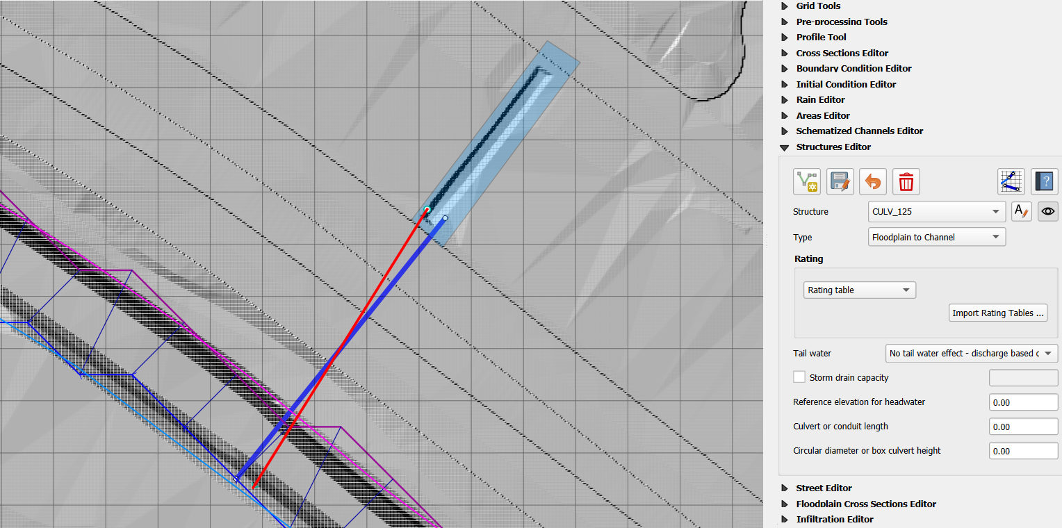
Step 4: Assign Structure Type and Review Structures
Identify structure types as either one of the following:
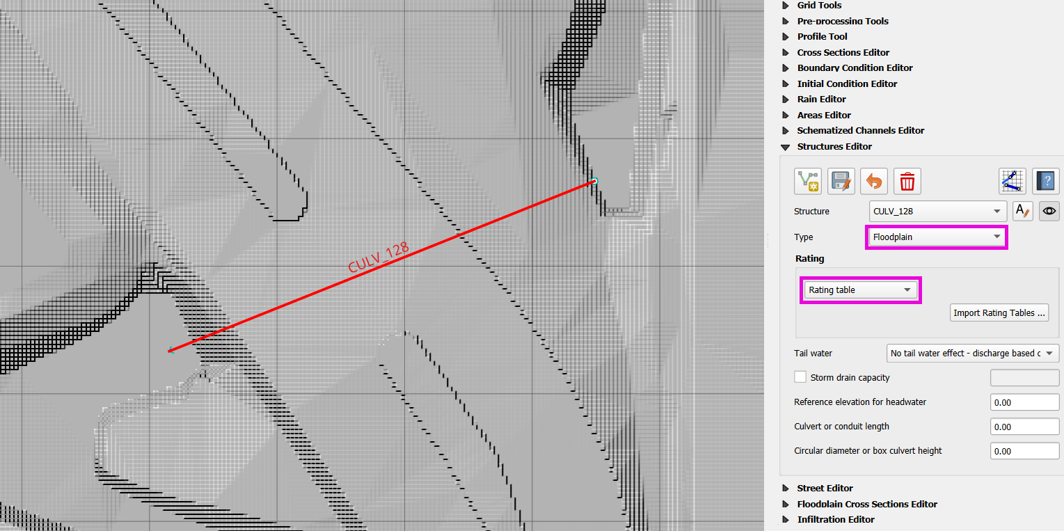
Floodplain to Floodplain
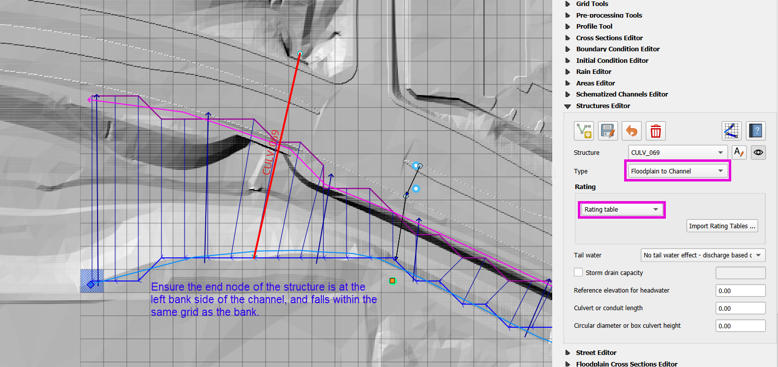
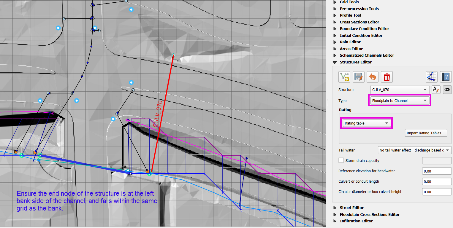
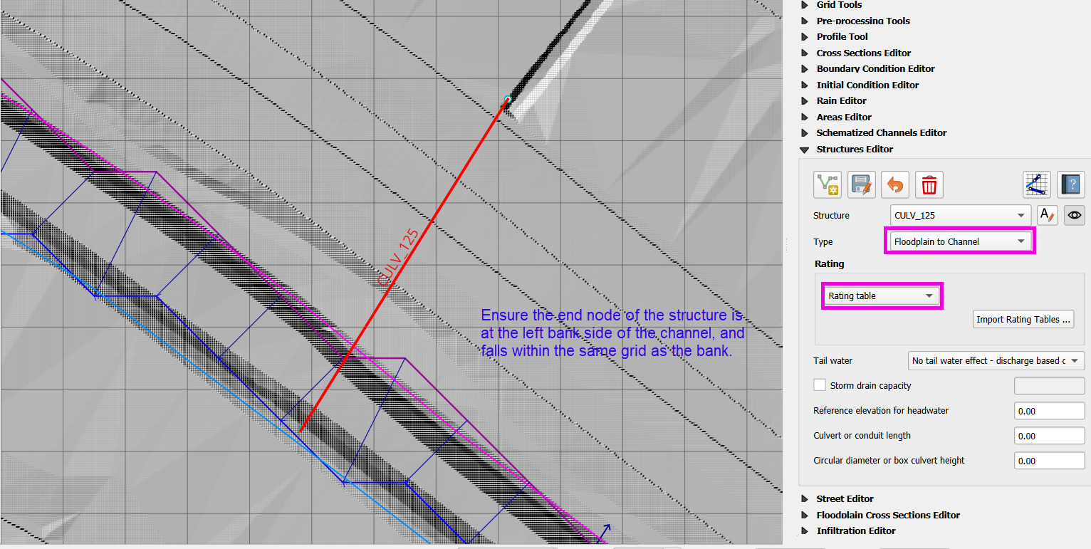
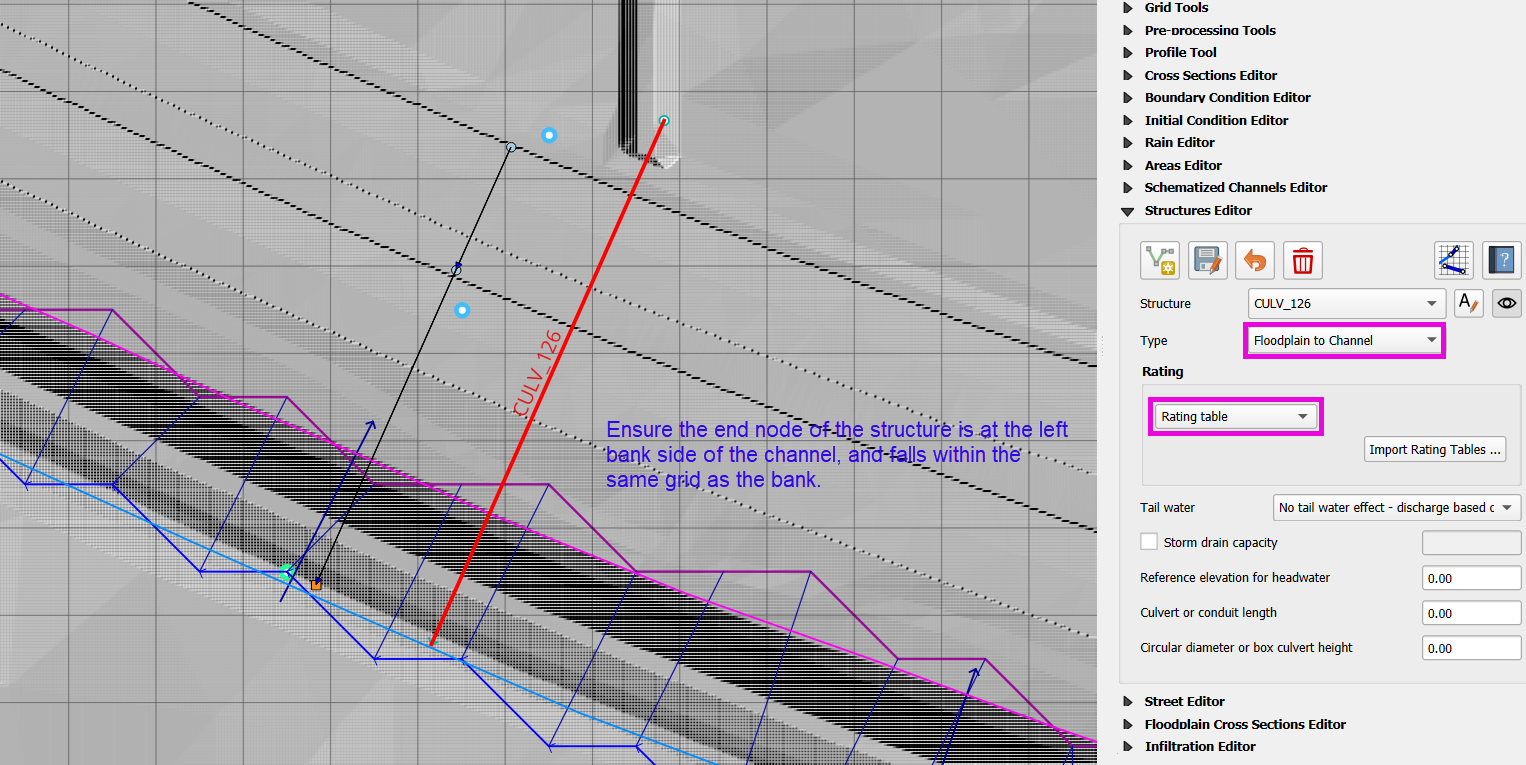
Floodplain to Channel (must be on a Left Bank node)
Channel to Channel (usually already handled in the channel lesson)
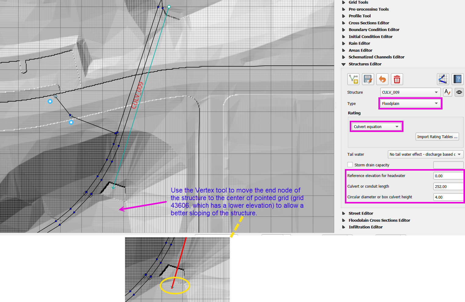
Where necessary, adjust hydraulic structure endpoints:
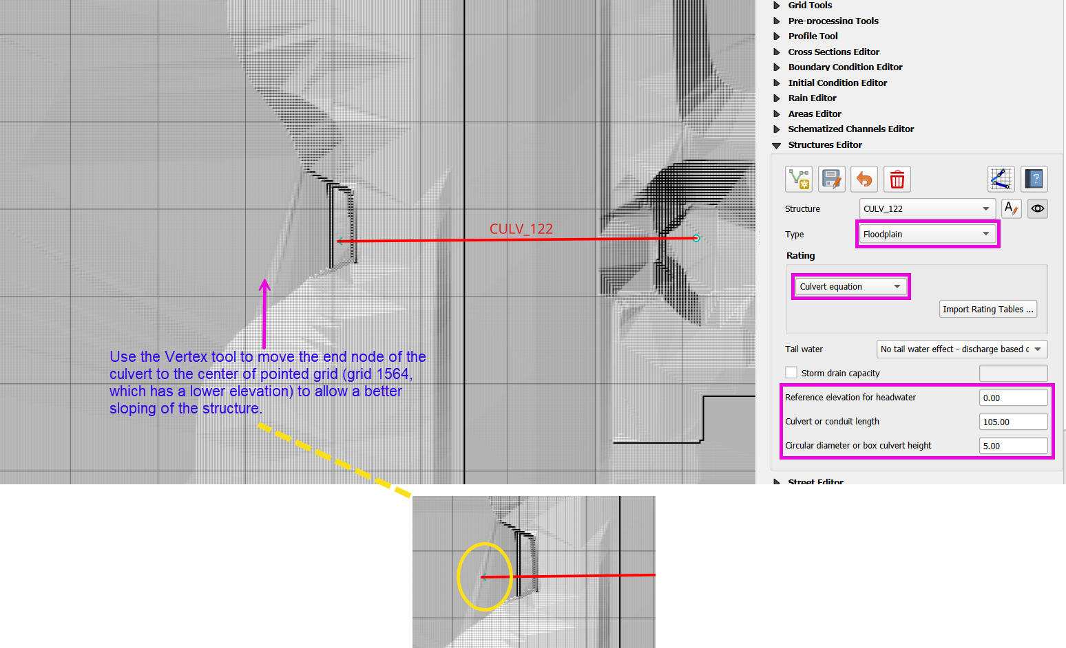
Use the Vertex Tool to move hydraulic structure endpoints to correct elevations or grid elements.
Note
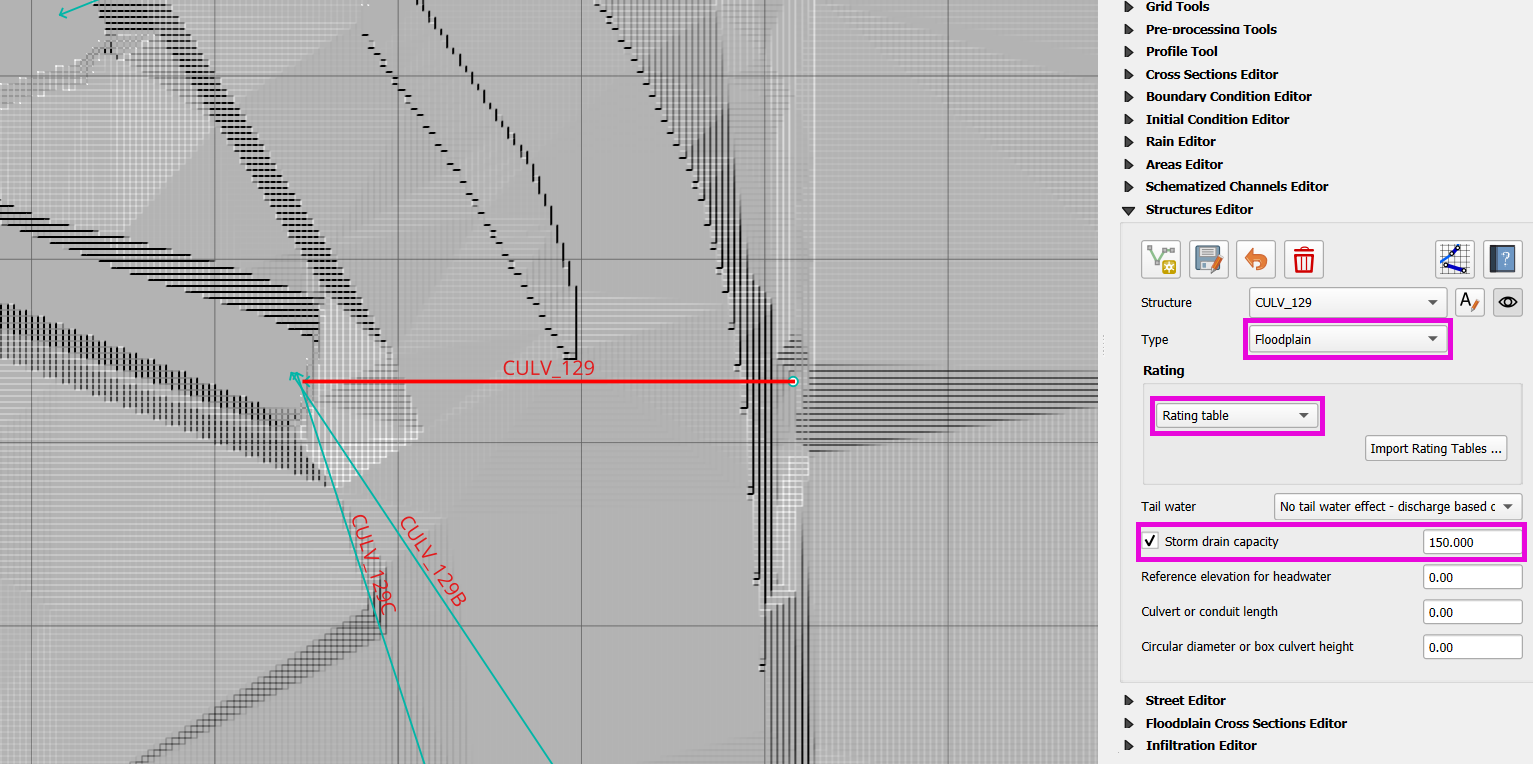
For grouped culverts (e.g., simple storm drain systems), assign a storm drain capacity in CFS.
For Floodplain to Channel hydraulic structures, assign the structures to the left bank because the left bank is the reference to the cross-section.
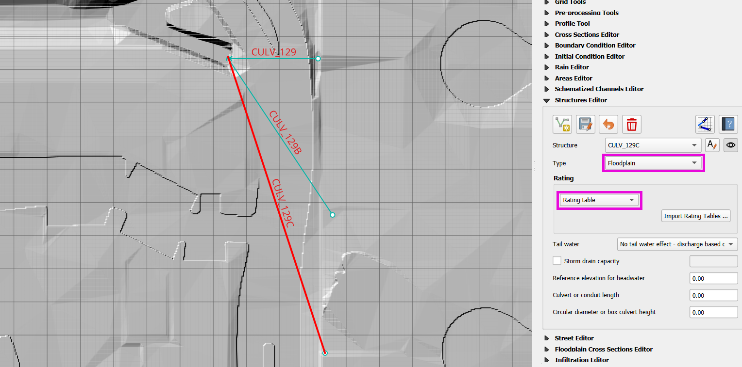
Step 5: Rating Tables and Culvert Equations
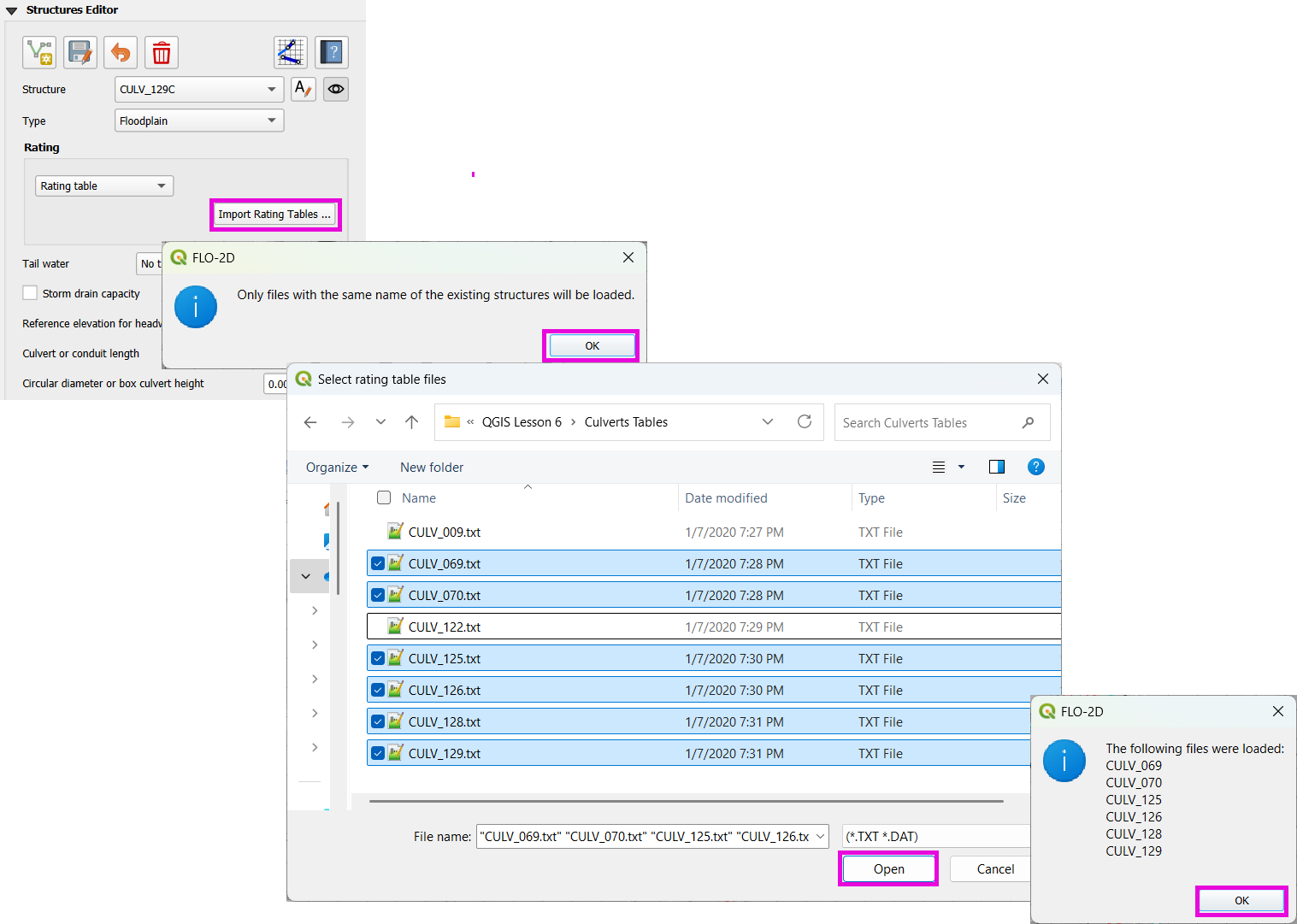
Step 5(i): Import Rating Tables
From the
Culverts Tablesfolder, select all files and import except CULV_009.txt and CULV_122.txt.Only rating tables that match existing structure names will be applied.
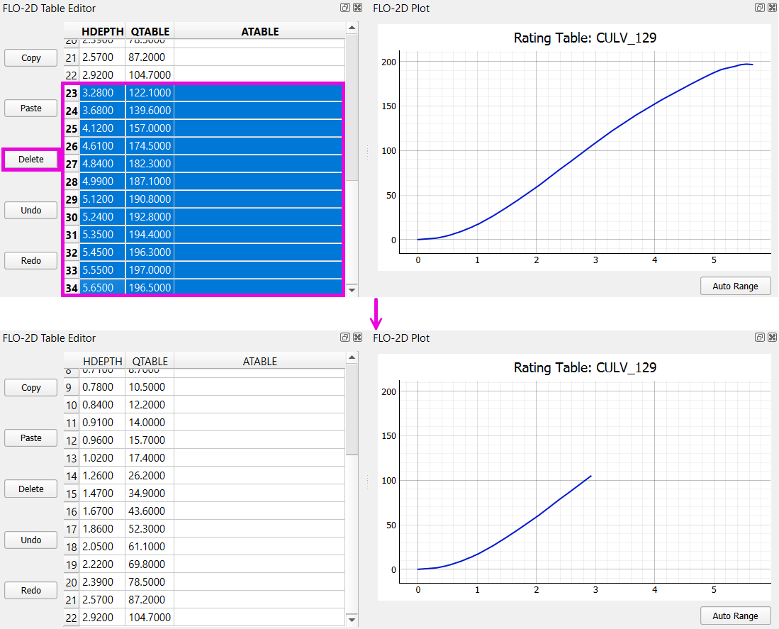
Manually Modify a Rating Table
Example: reduce max headwater for
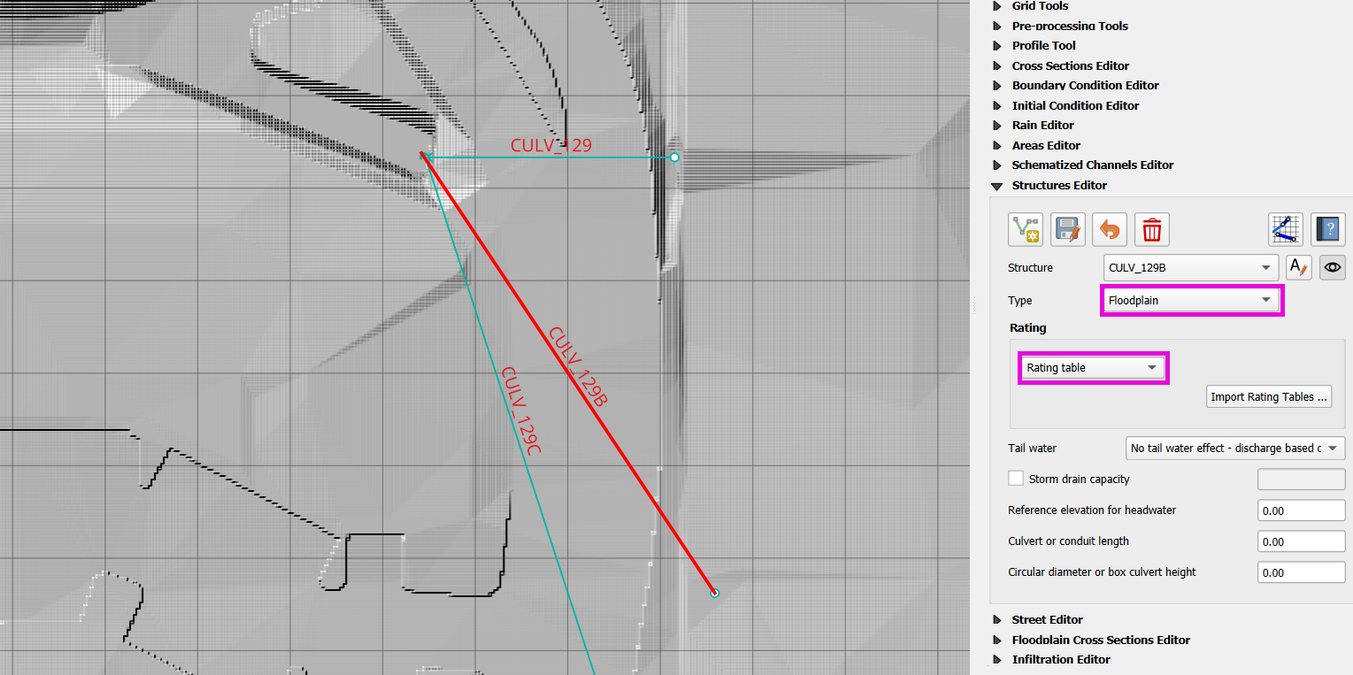
129,129B,129Cto approx. 3 feet.Delete rows from 3.0+ ft.
Copy and paste modified table to the other two structures (
129B,129C).
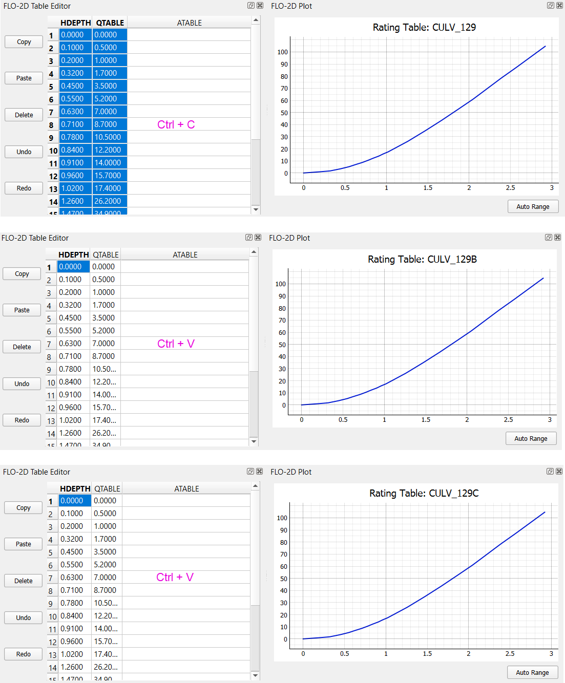
Note
Use Ctrl + C and Ctrl + V or Copy/Paste buttons.
If need be, use “Auto Range” button to get a better plot.
Step 5(ii): Review the Generalized Culvert Equations (GCE)
Fill the following properties for structures CULV_009 and CULV_122:
Conduit Length.
Diameter/Height.
Culvert Type (
TYPEC).Entrance Type (
TYPEEN).Culvert Manning’s n (
CULVERTIN).Entrance Loss Coefficient (
KE).Base (
CUBASE).Barels (
MULTBARRELS).
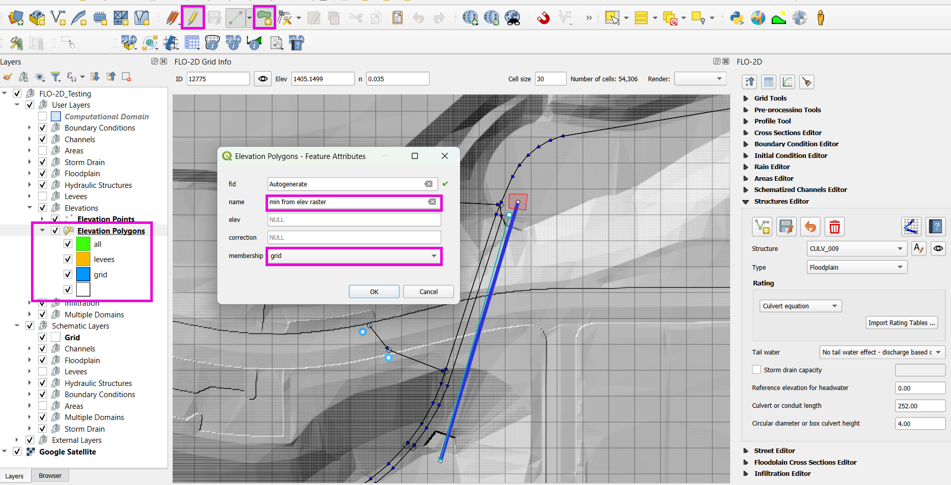
For culvert CULV_009 set the GCE parameters as follows:
Conduit Length: Measured to be 252 ft (headwall to headwall).
Diameter: 4 ft
TYPEC: 2 (circular)TYPEEN: 1 (square edge with headwall)CULVERTIN: 0.018KE: 0.5CUBASE: 0MULTBARRELS: 3
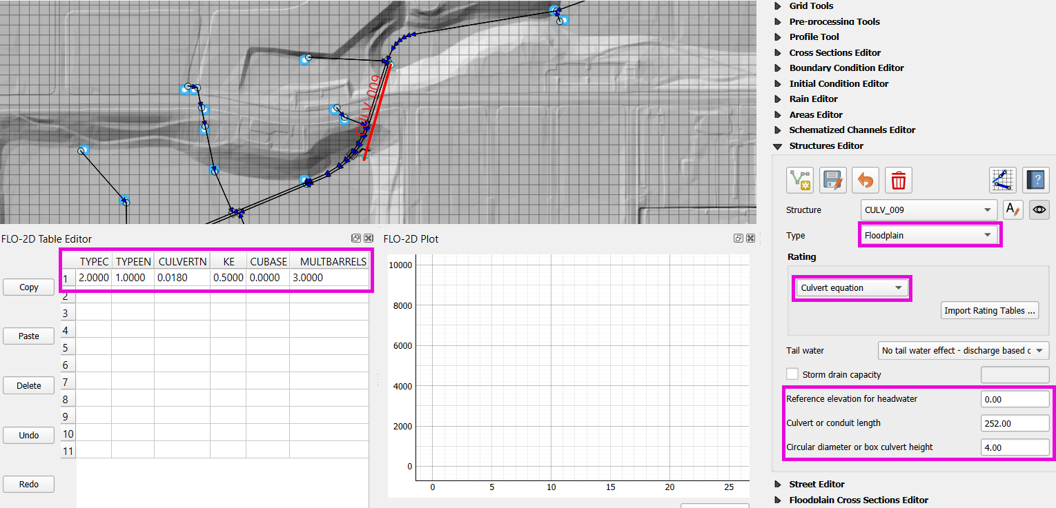
Note
These values are based on as-built drawings and Table C2 from HDS-5, 3rd Edition.
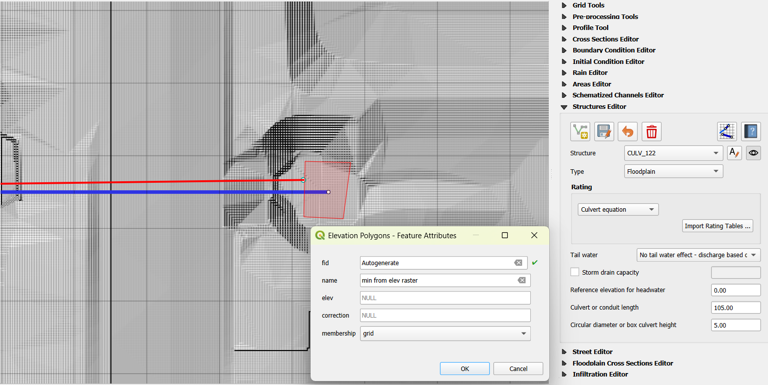
For culvert CULV_122 set the GCE parameters as follows:
Conduit Length: 105 ft
Height: 5 ft (Box Culvert)
TYPEC: 1 (wing wall 30°–75°)TYPEEN: 1 (box)CULVERTIN: 0.018KE: 0.4CUBASE: 8MULTBARRELS: 1
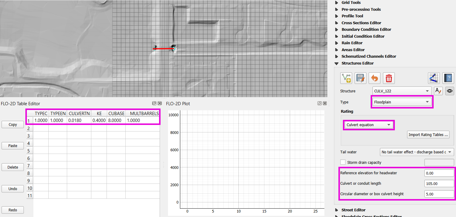
Note
From highway design manuals and HY-8 documentation
Image review confirms structure shape and inlet type
Tip
Culvert or conduit length can be measure directly in QGIS using the Measure Line tool.
Schematic Correction and Recheck
Save and click Schematize to update geometry.
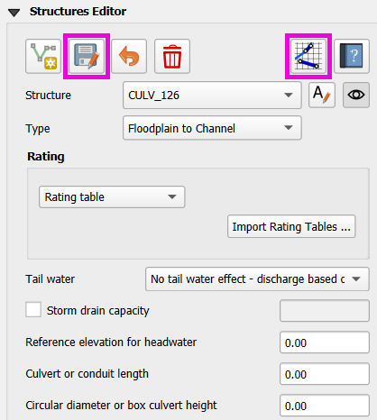
Check and re-validate structure assignments one more time.
Use the Center button to cycle through and verify again.
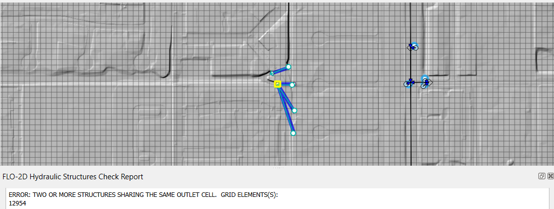
Warning
The following image illustrates a Simple Storm Drain configuration, which provides a convenient way to connect multiple inlets to a single outlet using a shared rating table and an outlet flow limit.
In this configuration, flow allocation among inlets is not governed by hydraulic conditions. Instead, inlet priority is determined solely by the internal index order of the inlets.
As a result, upstream inlets with lower index positions may preferentially pass flow while downstream or higher-indexed inlets may be artificially restricted once the outlet capacity is reached. This behavior can lead to non-physical flow distributions when multiple inlets compete for a constrained outlet.
This method should only be used when inlet prioritization by index is acceptable or hydraulically insignificant. For cases requiring hydraulically realistic flow sharing, a more detailed storm drain representation is recommended.
Correct Elevation
This lesson covers how to make elevation corrections for hydraulic structures, set up minimum elevations, apply levees, and prepare the model for export and run.
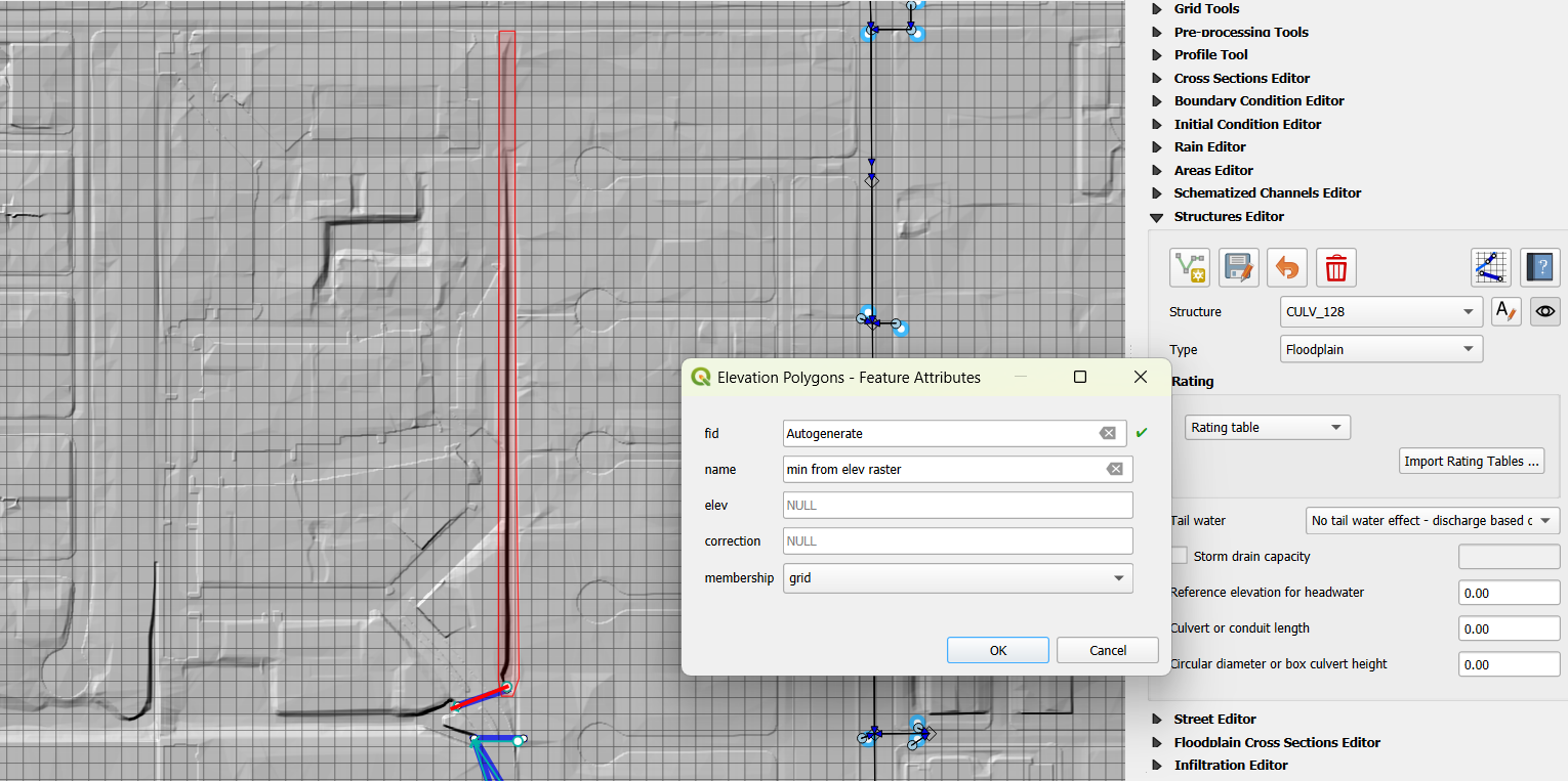
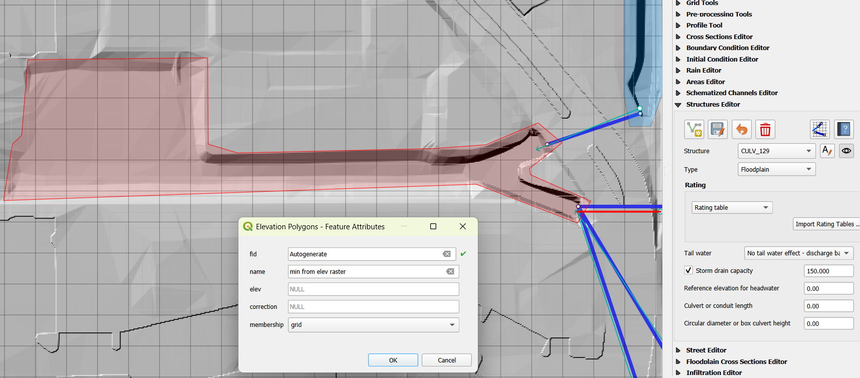
Step 1: Create Elevation Polygons
Go to the Elevation Polygons layer.
Start editing and click Add Polygon.
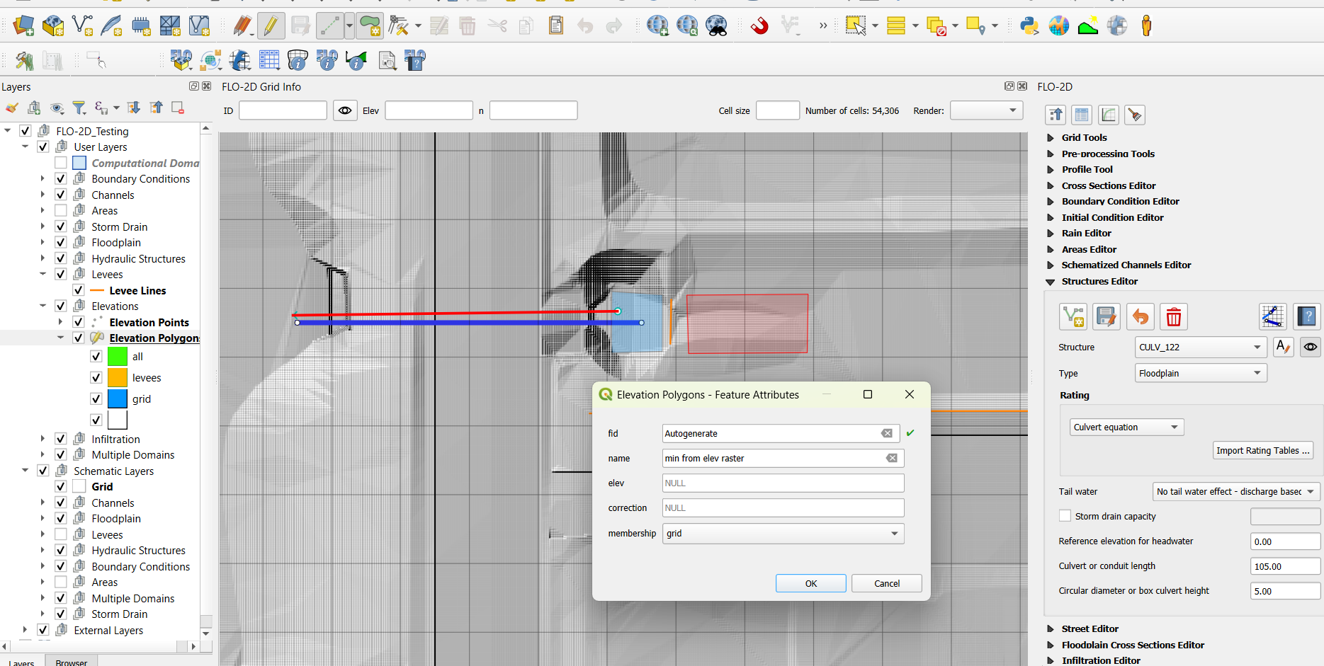
Set the name to
min from elev rasteror similar.Set method to
grid; leave other valuesnull.For simple corrections, draw a polygon around the centroid of the grid element you want to modify.
For complex corrections, select multiple grid cells and draw a polygon.
The attributes table of
`Elevation Polygons`should now be looking as the one shown below: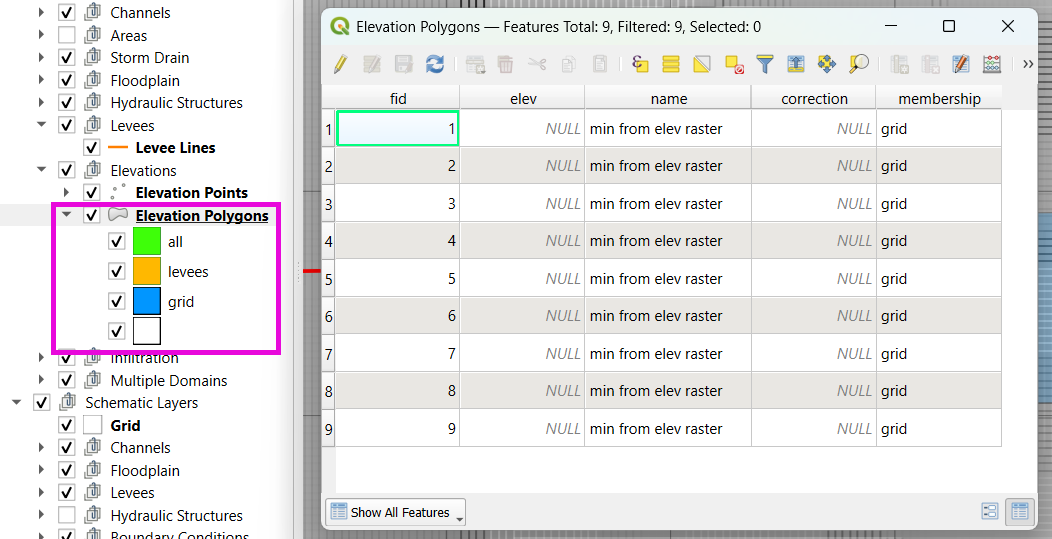
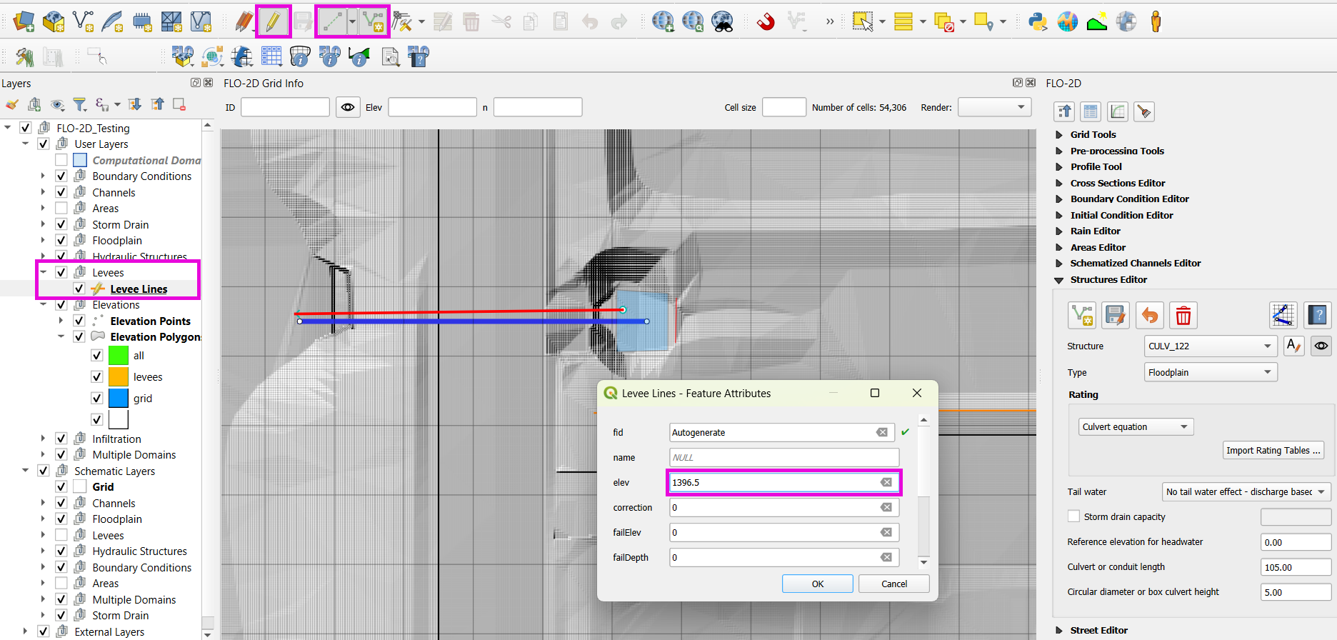
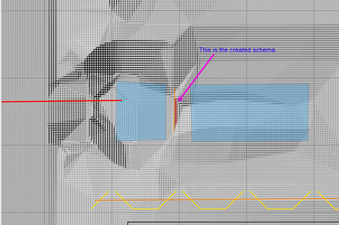
Step 2: Apply a Levee
Use the Levee Line tool to draw a line where flow should be restricted.
Assign the crest elevation based on sampled raster value (e.g., 1396.5).
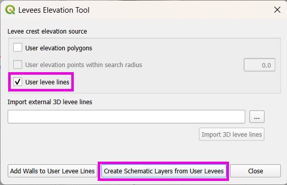
Reprocess the levees using:
Plugins > FLO-2D > Create Schematic Layers from User LayerswithLevee Lineschecked only.
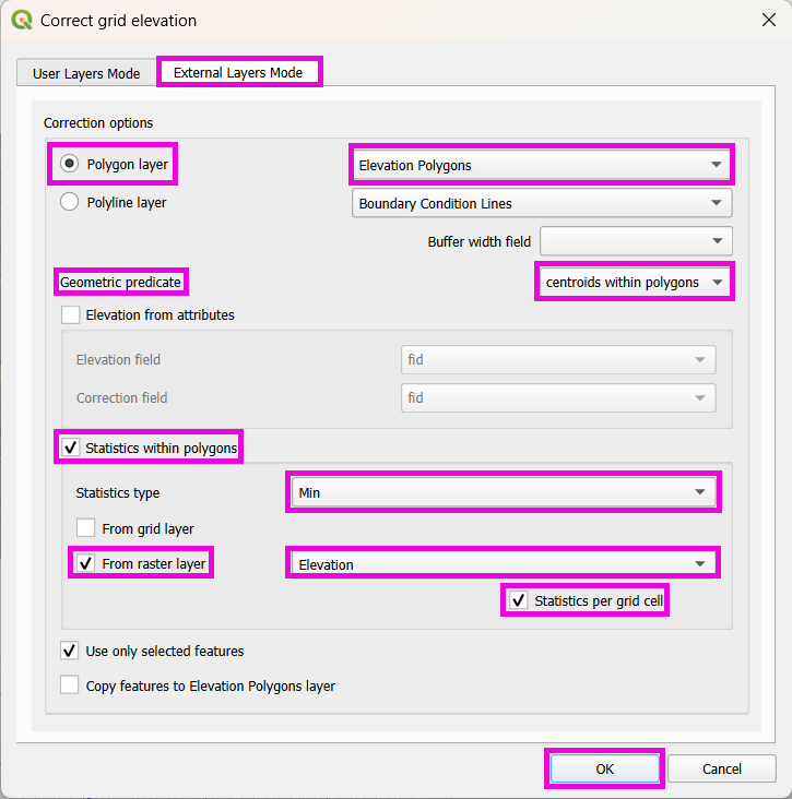
Step 3: Apply Grid Element Corrections
Use External Layer Mode
Set layer:
Elevation PolygonsCheck:
Centroids within polygonsSelect:
Statistics from rasterChoose
Minimum elevationCheck:
Statistics per grid element.
Note
These steps ensure correct invert elevations, allow headwalls to collect water properly, and ensure flow can pass over levees or into hydraulic structures.
Tip
After corrections, verify grid elevations with the Identify tool to confirm changes.
Step 4: Save, Export and Run
This short lesson walks through saving hydraulic structures, exporting the data, and running the model. It is part of the final steps for preparing your model.
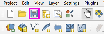
Click the QGIS Save button to commit your hydraulic structures to the layer in the GeoPackage.
Note
You do not need to turn on the export switch again if it was already activated when setting up channel hydraulic structures.
Export DAT files to a folder with a name like:
post elev change and correction
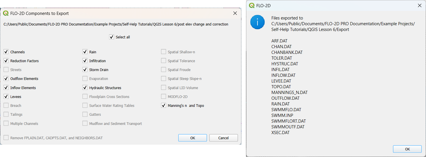
Run the model.
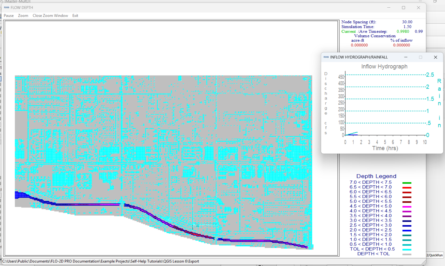
Note
If there is no error.check file generated, it means your data was set up correctly.
Warning
Although the model runs, the results may still be inaccurate due to elevation issues. These will be addressed in the next lesson.
Summary and Review Project
Under Construction…