Buildings and Walls
Setup up Buildings and Walls using Open Street Map Downloader, QGIS, and the FLO-2D Plugin.
Note
It will be easier to view these videos on YouTube. The step by step instructions are faster to follow but the videos are more detailed.
Set the video playback speed to 2x to complete the lessons faster.
The videos are more detailed whereas the text gives the minimum steps needed to complete the project.
Load and Assign Data
This lesson explains how to import and assign buildings in your FLO-2D model, including visualization tips and parameter configurations.
Step 1: Import Building Data
Locate the buildings shapefile from the Lesson 4 folder.
Drag and drop the shapefile onto the map canvas in QGIS.
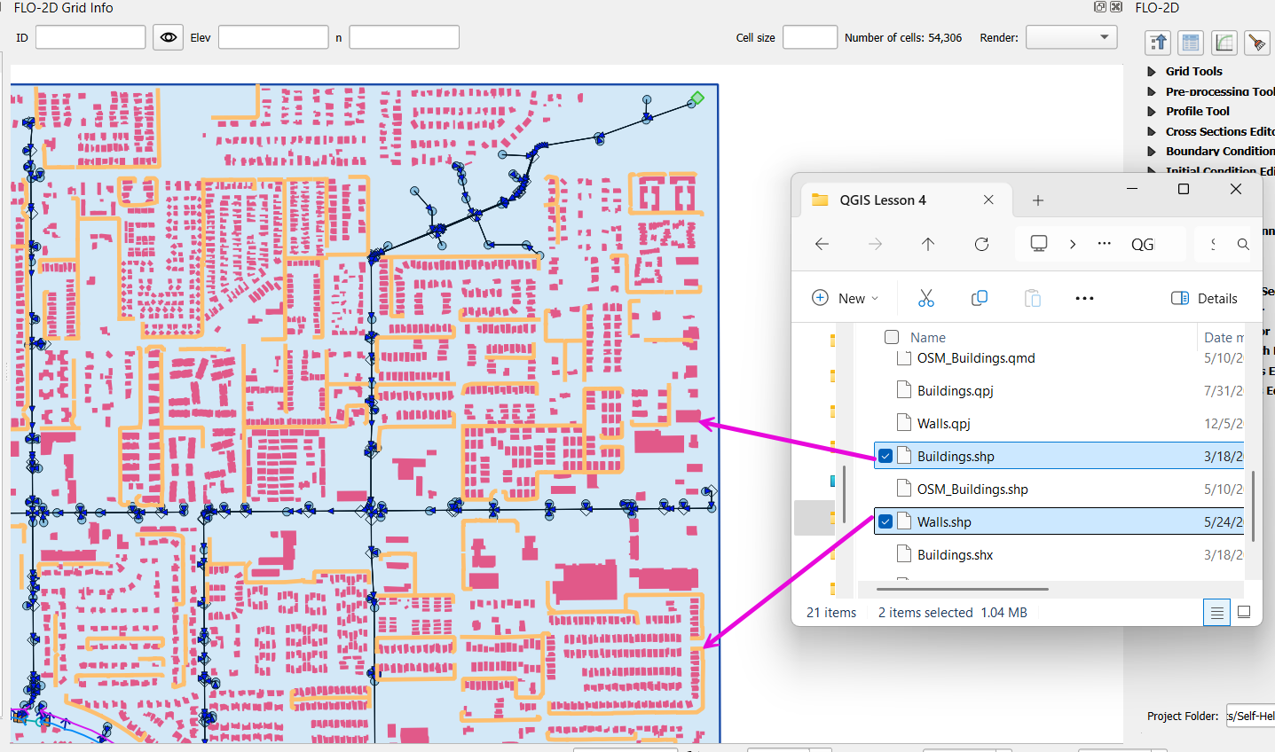
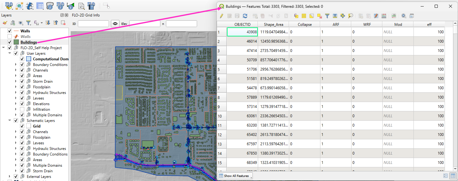
Step 2: Check Building Attribute Table
Open the attribute table to confirm the following required fields:
collapse: whether a building collapses during simulation (used in dam breach or large river simulations).ARF(Area Reduction Factor): adjusts flow for shallow overland flow.WRF(Width Reduction Factor): adjusts channel width for flow routing (rarely used).
Note
For urban simulations, only ARF is typically required.
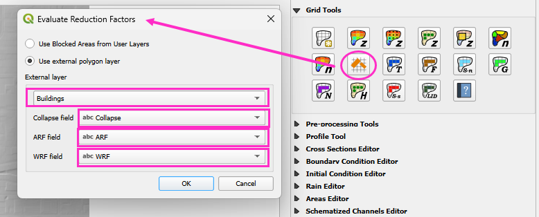
Step 3: Calculate Reduction Factors Using Grid Tools
Open Grid Tools.
Click the Calculate Reduction Factors button.
Set the following parameters:
Layer: buildings
Collapse Field:
collapseArea Reduction Field:
ARFWidth Reduction Field:
WRF
Click OK to apply.
This process will:
Create a blocked areas layer representing building footprints.
Update the schematized data to reflect buildings in the model.
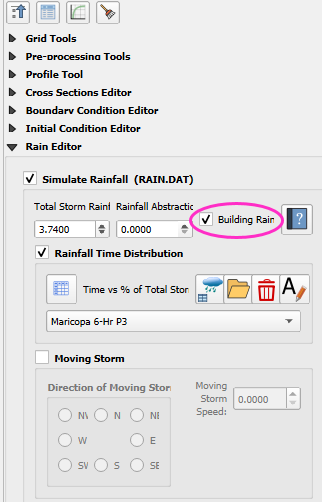
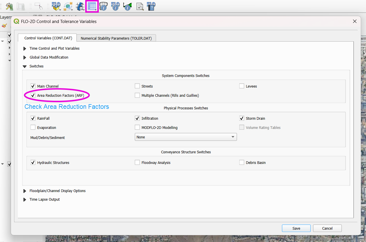
Step 4: Building Rain Switch
Ensure your rainfall setup includes the Building Rain Switch. This makes rain that falls on blocked cells flow off the building and onto surrounding grid elements. The grid elevation will determine the flow direction.
Turn on the Building Switch (ARF switch) in the FLO-2D Controls.
Click Save Components.
Important
If you forget to activate the building switch, buildings may act as sinks instead of obstructions.
Download Building Polygons (Optional)
Download Building Polygons
This tutorial covers how to obtain building data using OpenStreetMap (OSM) and prepare it for FLO-2D modeling. This process is useful when client-provided data is unavailable.
Step 1: Install the OSM Downloader Plugin
Go to Plugins > Manage and Install Plugins.
Search for OSM Downloader.
Click Install.
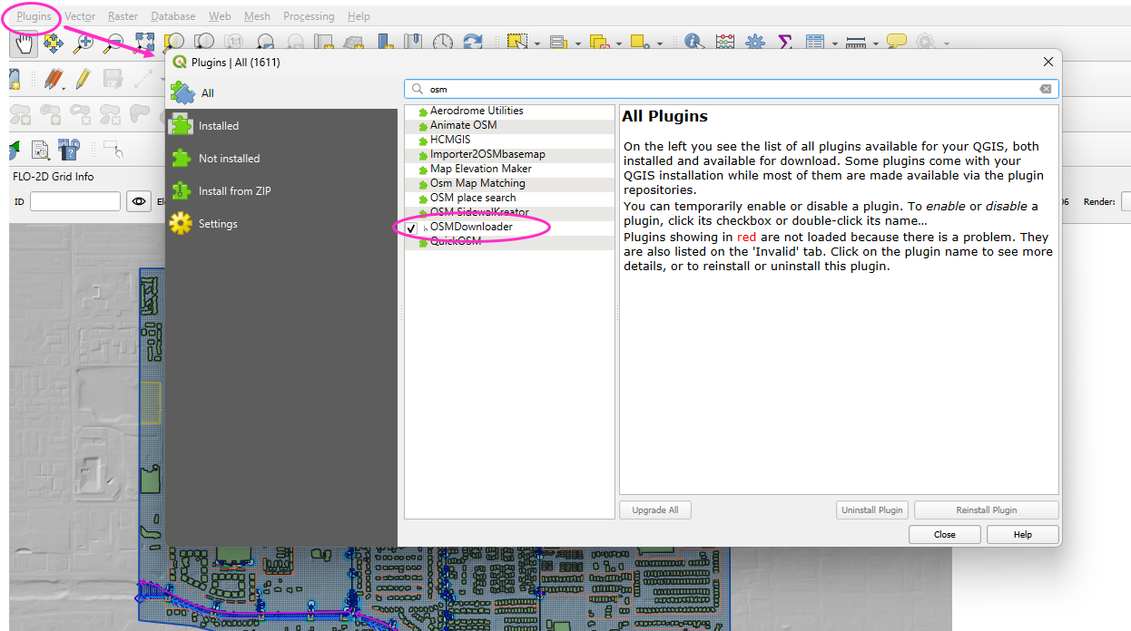
Tip
The OSM Downloader button is nearly transparent. Toggle it on/off to locate it in your toolbar.
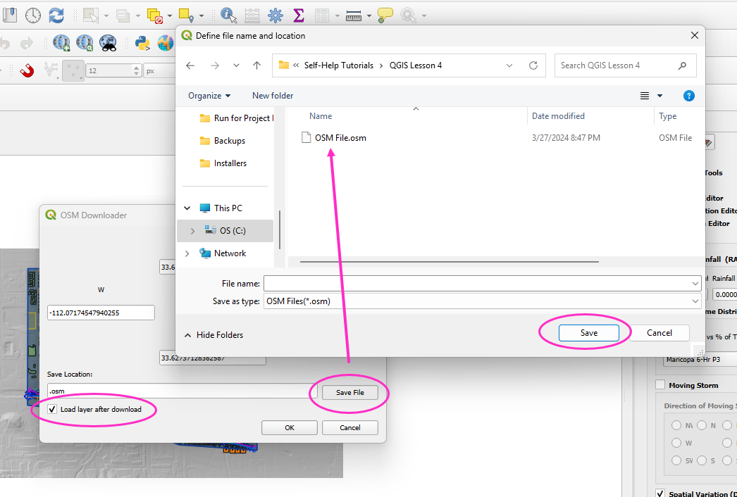
Step 2: Download Data
Activate the OSM Downloader tool.
Draw a rectangle around your project area.
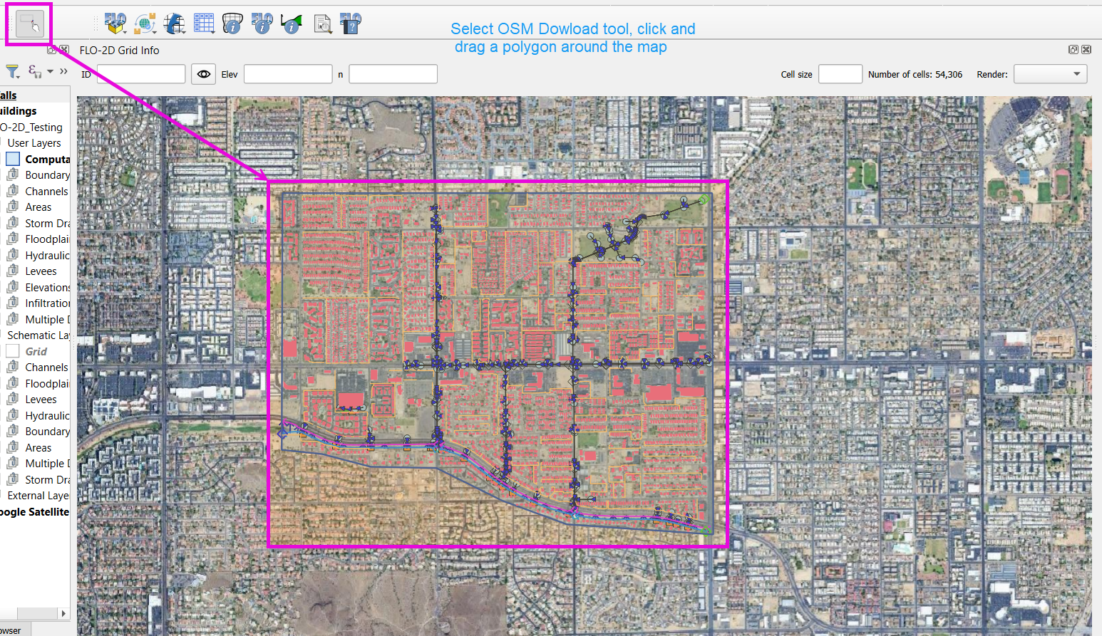
Save the file with a clear name like
osm_file.geojson.The data is downloaded in EPSG:4326 and will be reprojected later.
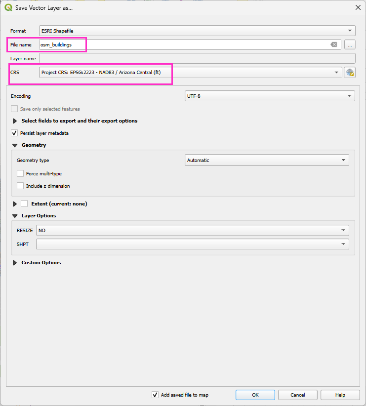
Step 3: Export Polygons
Turn off unnecessary OSM sublayers (e.g., roads).
Right-click the polygons layer > Export > Save Features As…
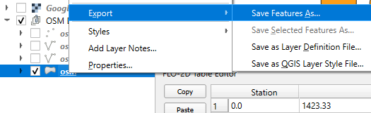
Save as
osm_buildings.Change the CRS to your project CRS (e.g., EPSG:2223).
Remove irrelevant fields before exporting.
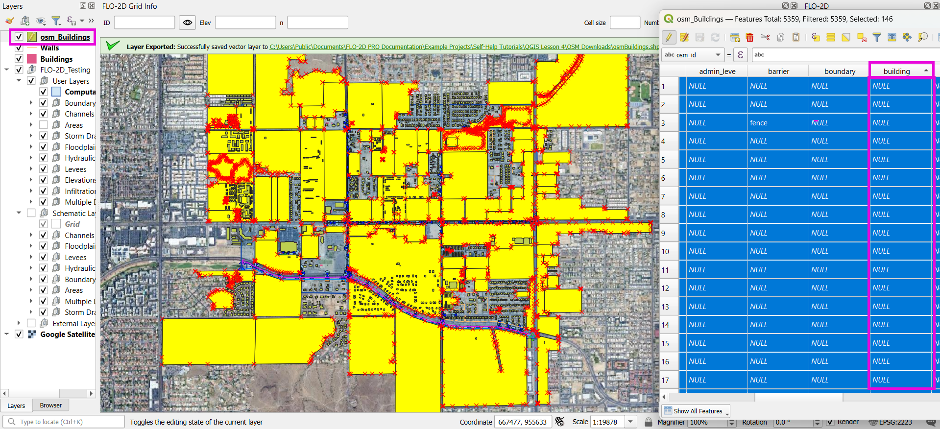
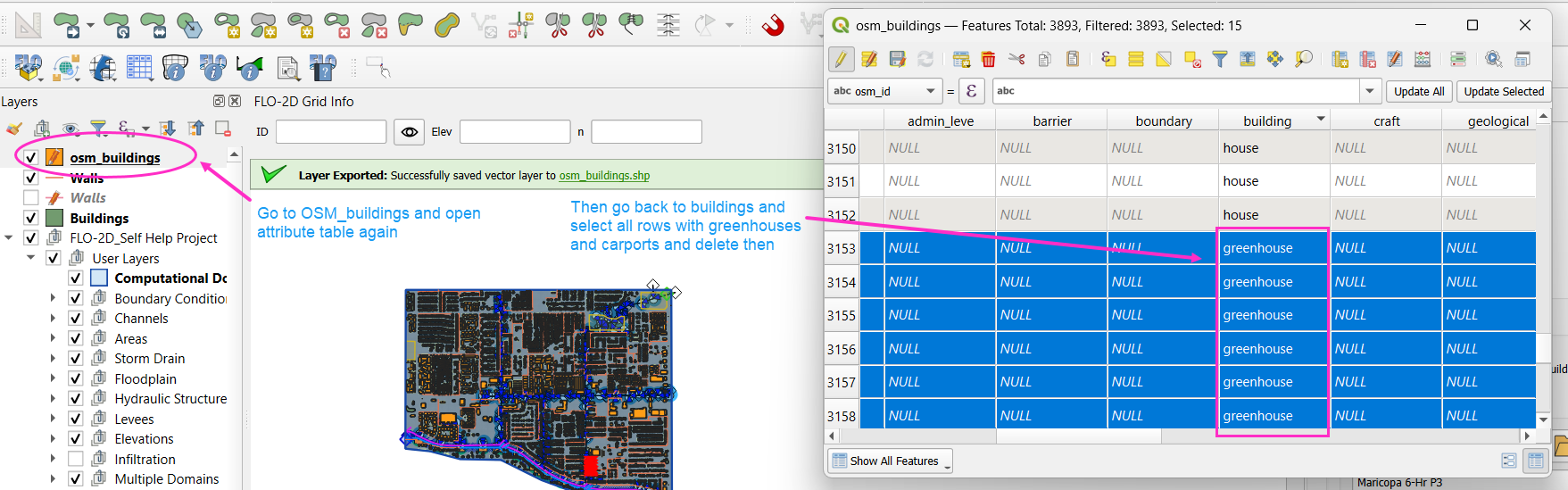
Step 4: Filter for Buildings
Open the attribute table.
Sort by the
buildingfield.Select rows where
buildingis null or empty and delete them.Save your edits.
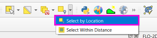
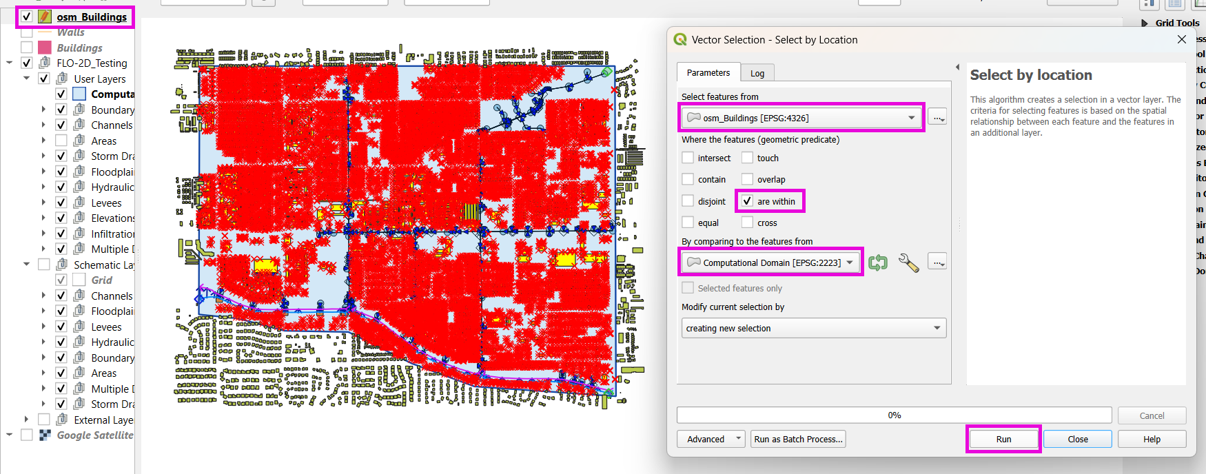
Step 5: Crop to Project Boundary
Use Select by Location:
Select features from
osm_buildings.Where the feature is within the computational domain layer.
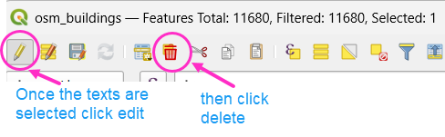
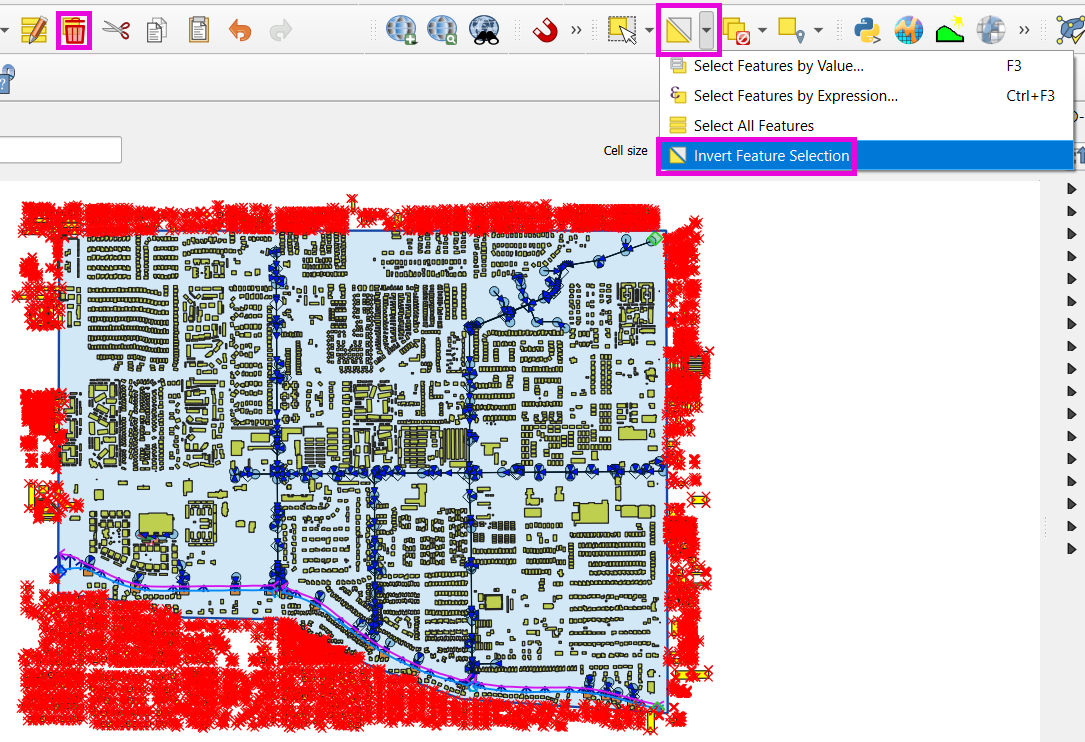
Use Invert Feature Selection tool and the Delete button to delete unselected features (those outside the project area).
Step 6: Clean Building Types
Review building types.
Delete features such as
carports,gas islands, etc., which don’t obstruct flow.
Step 7: Fill in Missing Buildings (Optional)
Turn on a satellite basemap (e.g., Google Satellite).
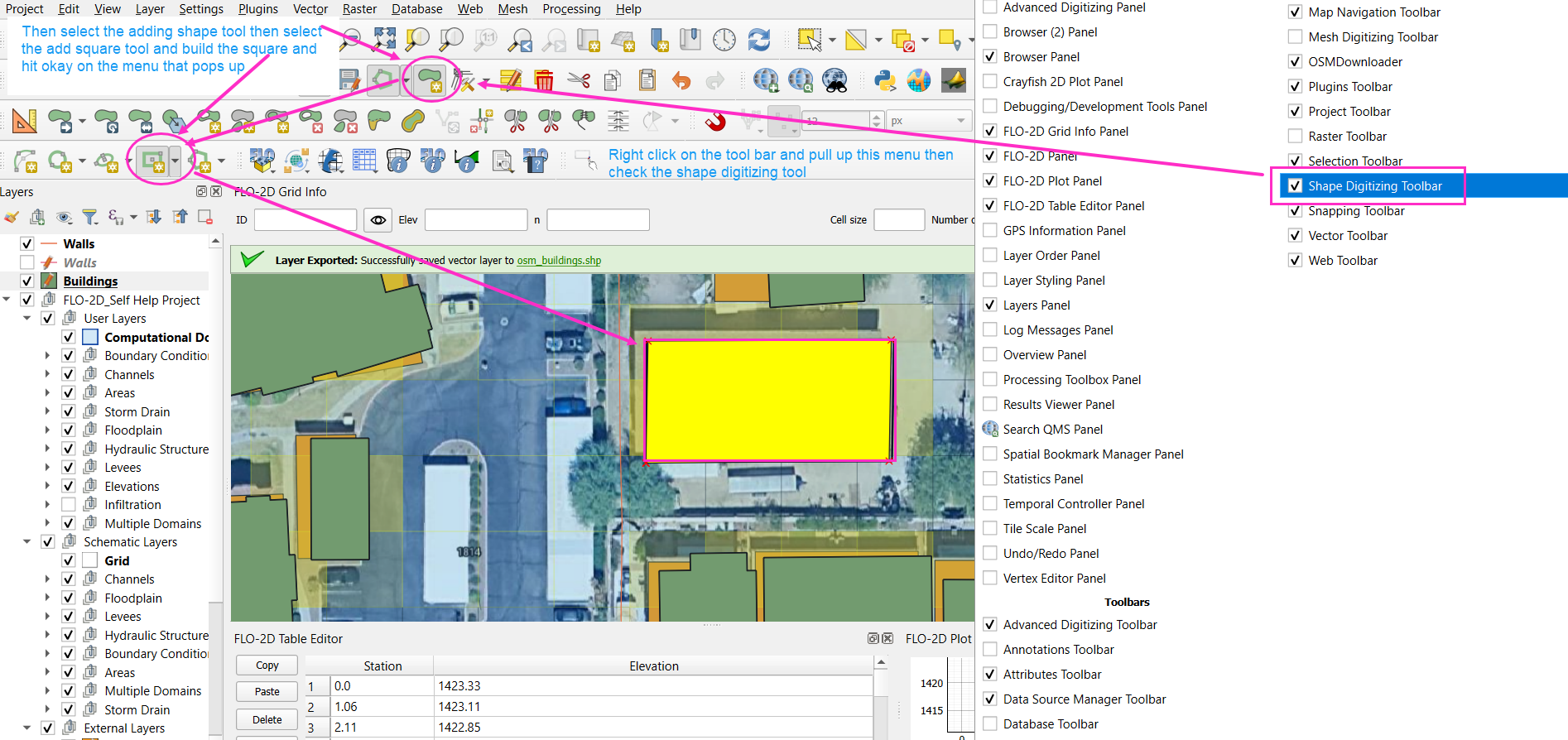
Use the Add Polygon tool or Shape Digitizing Toolbar to:
Digitize missing buildings.
Use
Rectangle from Extentfor fast creation.Use
Digitize with Segmentfor complex shapes.
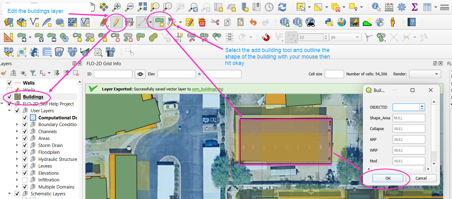
Tip
Or you can try the Add Polygon tool to draw buildings manually.
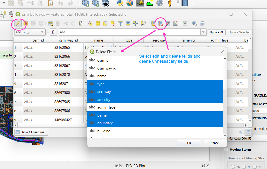
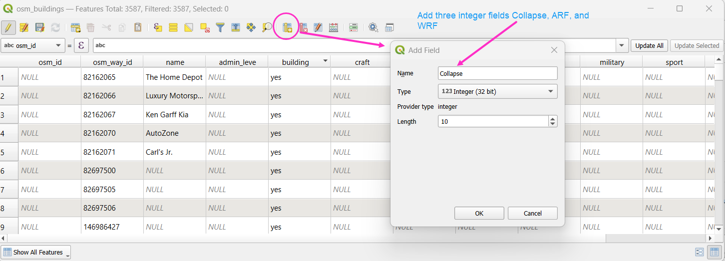
Step 8: Add Required Fields
Add the following integer fields:
collapseARF(Area Reduction Factor)WRF(Width Reduction Factor)
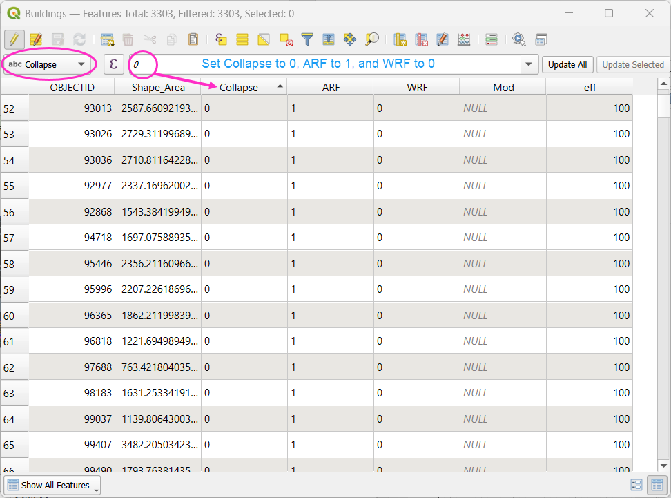
Use the Field Calculator to:
Set
collapse = 0Set
ARF = 1Set
WRF = 0
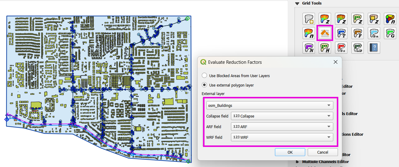
Step 9: Evaluate reduction factors
Open the Grid Tools and use the Calculate reduction factors (ARF and WRF) tool to calculate ARF and WRF.
Set the parameters as shown below.
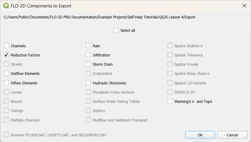
Step 10: Export the Final Building Layer
Save the edited buildings as a new layer if desired.
Export reduction factors.
Step 11: Review the `ARF.DAT` File
Open
arf.datin Notepad++. Key sections:Sline: global reduction factor (e.g., set to 0.5 to reduce all T lines to 50%).Tlines: fully blocked cells.Plines: partial blocks with ARF values < 1.0.
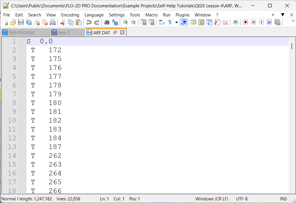
Tip
The model will automatically convert cells with high ARF values (e.g., > 0.95) to fully blocked.
Review and Assign Walls
Wall Setup and Failure
This lesson explains how to assign walls, set failure properties, and export wall data for FLO-2D modeling. Walls are common features in urban flood studies, especially in the southwestern United States. Unlike fences, these are usually concrete and can significantly change floodwater movement.
Note
These steps are based on QGIS 3.40 and FLO-2D Gila Plugin 2.0.
Step 1: Review Wall Data
Right-click the walls layer and select Open Attribute Table.
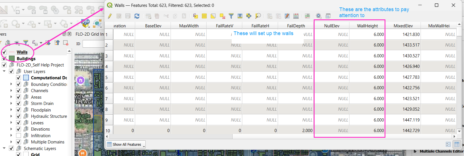
Identify the following fields in your table:
Ignore: FID, crest elevation, correction, mixed elevation, mixed height, elevation, and fail elevation.
Use: Set Wall height for your wall data.
For collapse properties, use fail depth and set other failure rate fields to zero.
Note
If the wall elevation is null, the processor will use the wall height to determine it.
Tip
Only keep hydraulically significant walls. Remove walls that do not affect flood routing, such as those inside large neighborhoods.
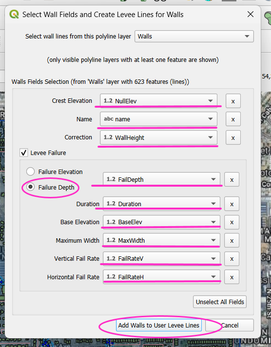
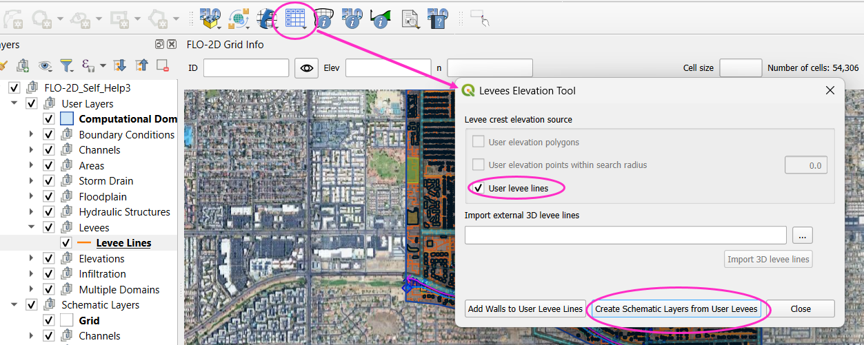
Step 2: Add Walls to User Levee Lines
Open the Levee and Wall Tool from the FLO-2D toolbar.
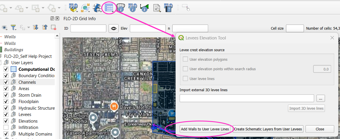
In the tool dialog:
Set Crest Elevation and Name to null.
Set Correction Field to Wall height.
Make sure all unused fields are set to zero or left blank as appropriate.
Set Failure Depth (e.g., 2 feet) in the correct field.
Click Add Walls.
Step 3: Convert Levee Lines to Schematic Layers
In the Levee tool, click Create Schematic Layers from User Levee Layers.
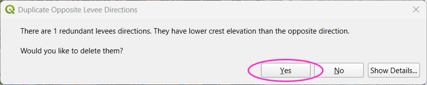
Choose whether to add to existing layers or create new ones.
If prompted about redundant levees, click Yes to remove them.
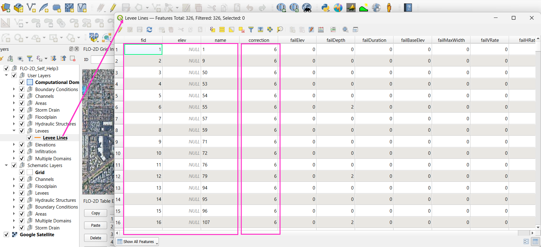
This is what the Levees look like.
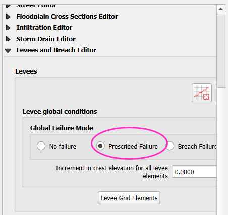
Step 4: Prescribed Failure Setup
Open the Levee Editor.
Enable Prescribed Failure for the wall lines.
Export the levee data again.
Check the export folder. The lev.dat file should now show prescribed failure (with a value of 1).
Buildings and Walls Summary
This lesson summarizes the process of setting up buildings and walls in FLO-2D, including importing data, assigning parameters, and exporting for simulation. It’ll just be a video.
Save Export and Run
This lesson walks through saving the FLO-2D project, exporting the required data, troubleshooting errors, and running the simulation.