Culverts#
Overview
This tutorial outlines the process of creating hydraulic structures with generalized culvert equations.
Required Data
File |
Content |
|---|---|
*.shp |
Culvert Data |
Data Location: \Coastal Training\Project Data\Culverts
NEED TO CHANGE THE YOUTUBE LINK
Step 1: Import data#
Start by cleaning up the map space so the next layer will be easy to see.
Uncheck the Channels group.
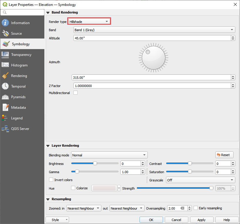
Check the Elevation Layer to run on the elevation map.
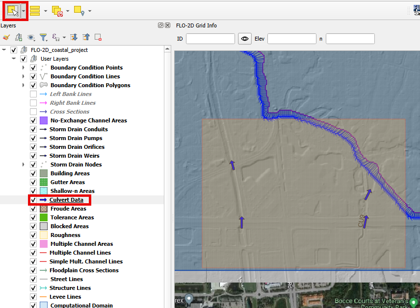
Click the Structure Lines layer to activate it. It is in the User Layers Group.
Drag the Culvert Data.shp onto the map space.
Step 2: Format the data layers#
Double click the Culvert Data layer.
Change the symbology to Arrow.
Set the Labels to structname.
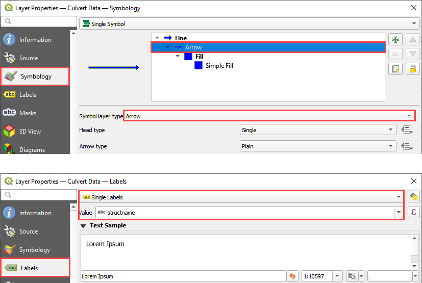
This helps identify the structure and show the flow direction.
Step 3: Build the structures into the User Layers.#
Important
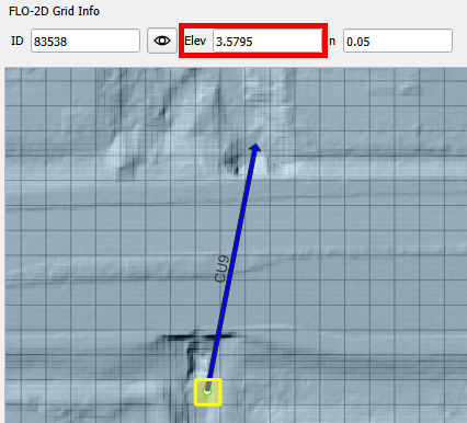
On FLO-2D, the Culvert must be created from upstream (higher elevation) to downstream (lower elevation). It is possible to check the elevations using the Grid Info Tool. The grid element elevation is used as the invert elevation of the culvert. If elevation corrections are needed, review the Advanced Hydraulic Structures lesson for the methods. It is found on the left sidebar.

Use the Structure Editor to add the new structures.
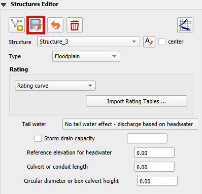
Collapse the Widgets, open the Structures Editor, and click the Add a Structure button.
Digitizing process:
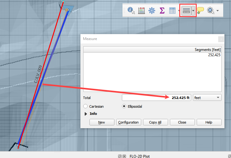
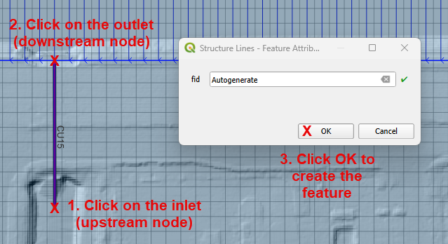
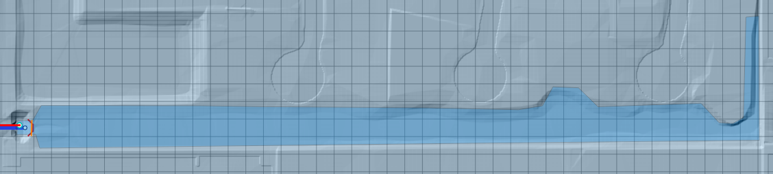
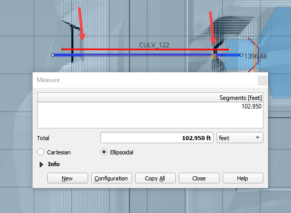
Locate Culvert #15 (CU15) on the right portion of the map, near the channel. In this Culvert, the water flows in the south-north direction.
Left click the inlet node (upstream node)
Left click the outlet node (downstream node)
Right Click to finish the polyline. Click OK to close the attribute window.
Click save on the widget to save and load the recently added data to the widget
Important
Utilize the Widget save button to save and load data into the Widget. Please note that using the QGIS save button adds the data but does not populate it into the Widget. If the QGIS save button was used, click on edit and save again using the Widget button to ensure the data is populated.
Copy process:
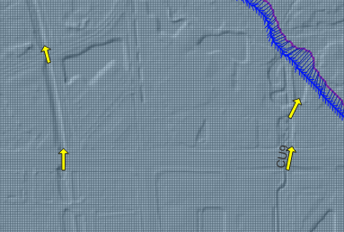
In order to speed up the live class, click on the Culvert Data layer and select the other 4 culverts
Culverts that are selected will be highlighted with a yellow color.
Use the Ctrl + c command to copy the selected Culverts from the Culvert Data layer. Select the Structure Lines layer, click on the Toggle Editing button and paste the Culverts using Ctrl + v.
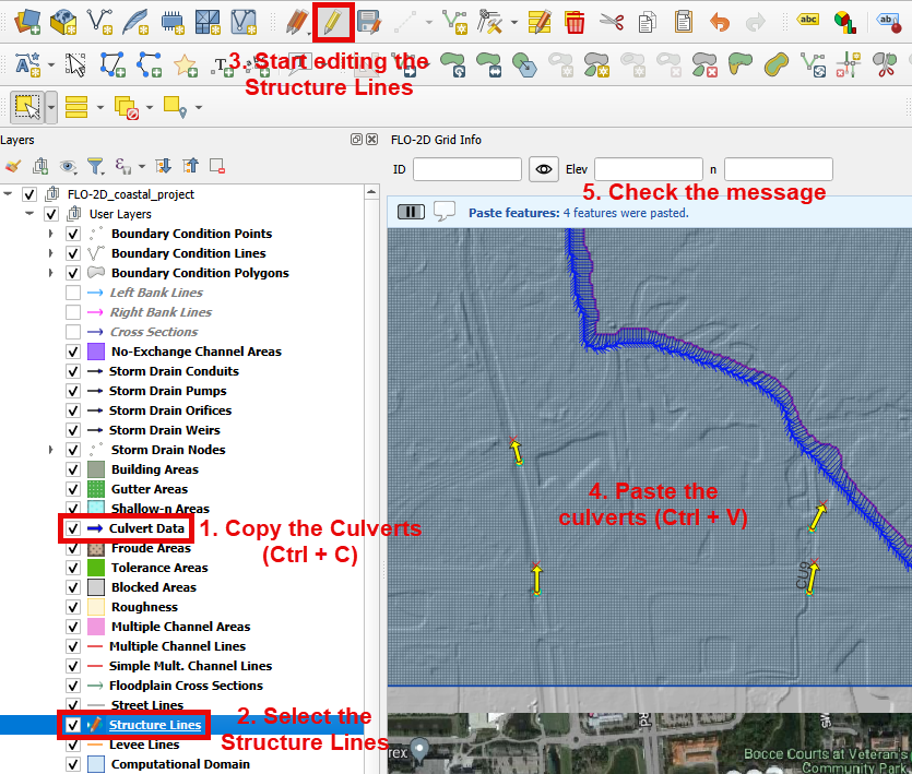
Click save on the widget to save and load the recently added data to the widget.
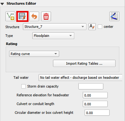
Step 4: Assign the structure attributes#
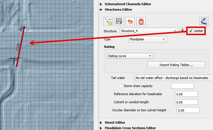
Check the center box.

To identify the Culvert Name, zoom into the selected feature. If the center checkbox is checked, it will be marked in red.
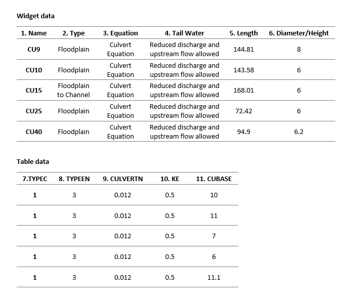
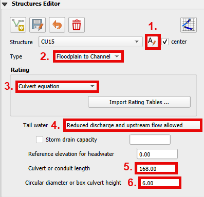
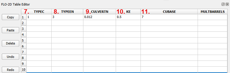
Start filling up all the data based on the following tables and figures.
Note
TYPEC
type 1: box culvert
type 2: pipe culvert
TYPEEN
BOX entrance:
type 1: wingwall flare 30 to 75 degrees
type 2: wingwall flare 90 or 15 degrees
type 3: wingwall flare 0 degrees
PIPE entrance:
type 1: square edge with headwall
type 2: socket end with headwall
type 3: socket end projecting
CULVERTN
Culvert Manning’s roughness coefficient. Default = 0.03.
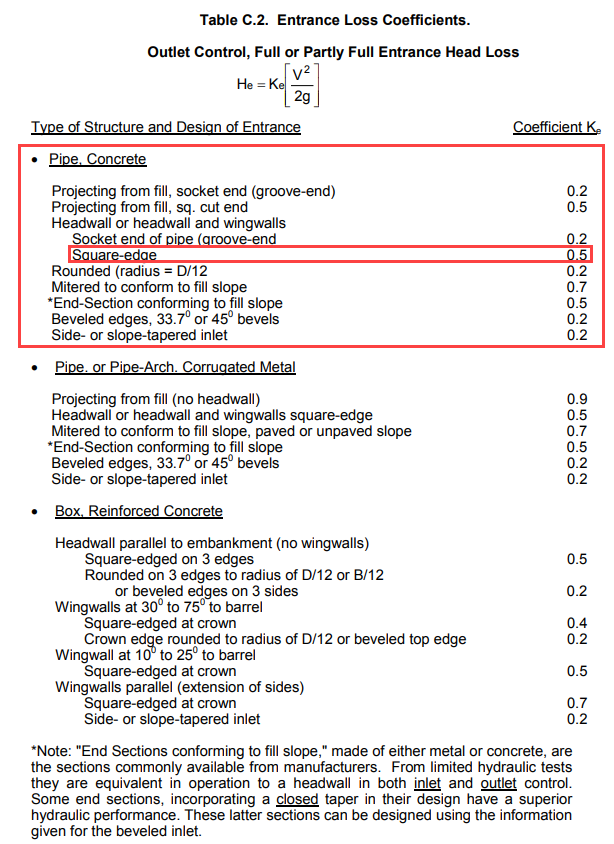
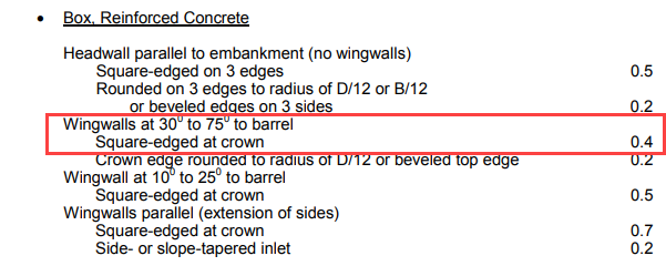
KE
Culvert entrance loss coefficient.
CUBASE
Flow width (ft or m) of box culvert for TYPEC = 1. For a circular culvert, CUBASE = 0.
See also
From Hydraulic Design of Highway Culverts - HDS-5-Third Edition
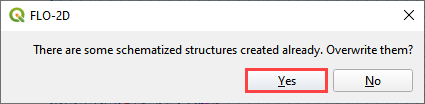
Schematize the structure data and click Yes to replace the data.
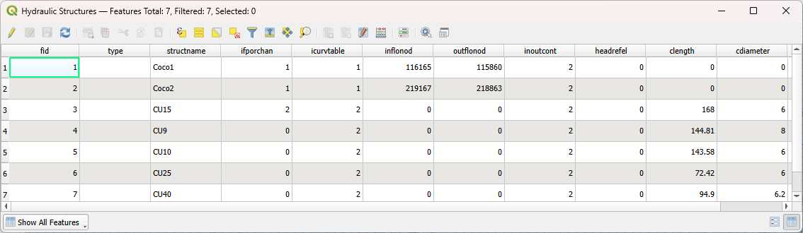
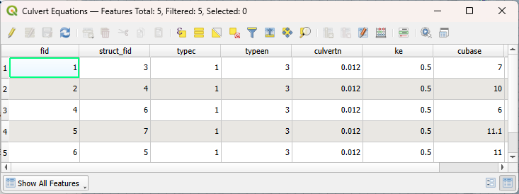
Note
To verify the added data, it is possible to open the attribute table of the Hydraulics Structures layer and the Culvert Equations table within the Hydraulic Structures group.
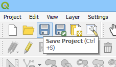
Step 6: Save, and export#
This is a good point to save project.
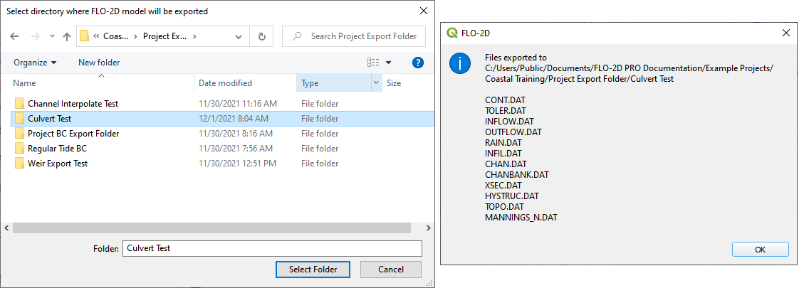
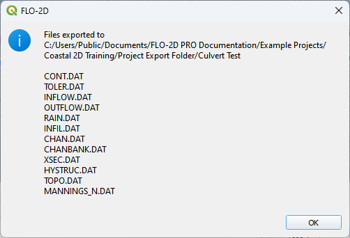
Export the data files to the Culvert Test folder.

All data files will be created in the selected project folder.
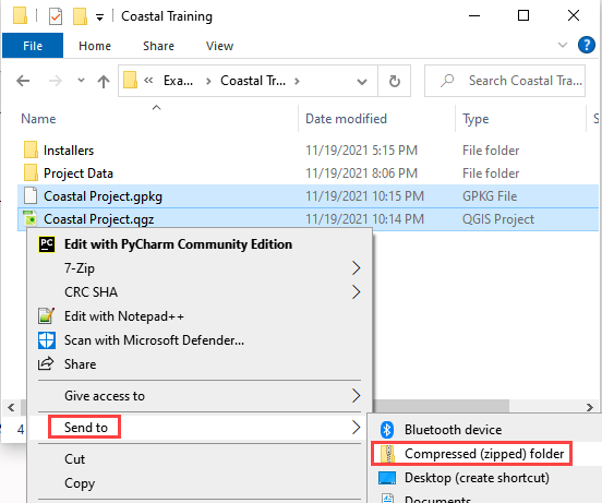
Step 7: Create a backup file#
Close QGIS.
Open the project folder. Select the Coastal Project.gpkg and Coastal Project.qgz files. Right click them and click Sent to/Compressed (zipped) folder.
Name the zipped file. It is good to choose a name that identifies project progress. For Example: CulvertsOK.zip
Open QGIS and reload the project.
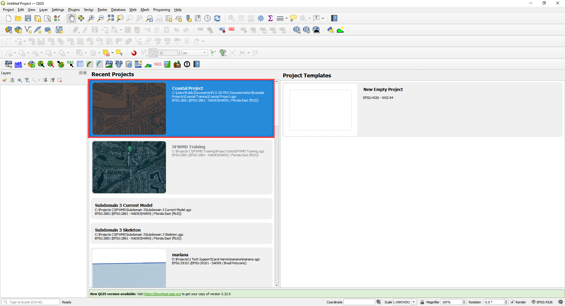
Click yes to load the model.