Lesson 6 – Hydraulic Structures#
Overview
Lesson 6 outlines the process of creating hydraulic structures with rating tables and generalized culvert equations. This lesson needs a channel so please use the data from QGIS Lesson 2, 3, or 4 to run through this tutorial.
This video shows the full process of this tutorial.
Required Data#
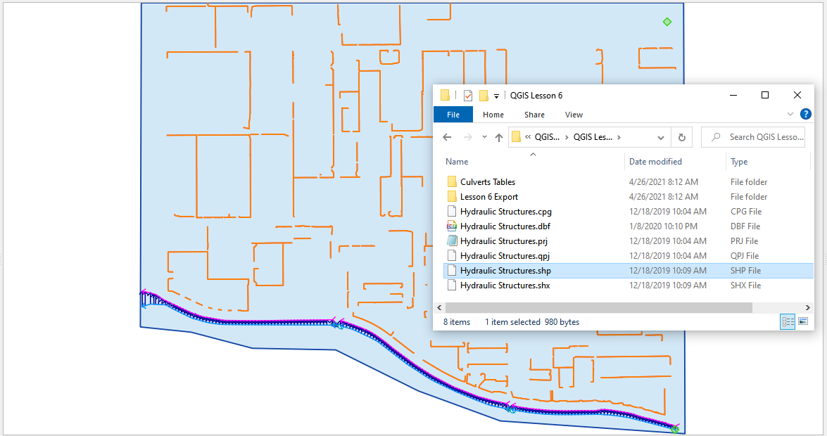
The lesson makes use of QGIS Lesson 2, 3, or 4 and hydraulic structure shapefile and structure data files in QGIS Lesson 6.
File |
Content |
Location |
*.shp |
Hydraulic Structures |
QGIS Lesson 6 |
*.txt |
Culvert Tables |
QGIS Lesson 6\Culvert Tables |
Project Location C:\Users\Public\Documents\FLO-2D Pro Documentation\Example Projects\QGIS Tutorials
Check these folders to ensure the data is available before starting the lesson.
Step-by-Step Procedure#
To build HYSTRUC.DAT following these steps.
Open Lesson 2, 3, or 4 qgz file;
Import the Hydraulic Structures shapefile;
Build the structures into the User Layers;
Assign the structure attributes;
Assign the rating tables;
Schematize the data;
Export and project;
Run the simulation.
Step 1: Setup the project#
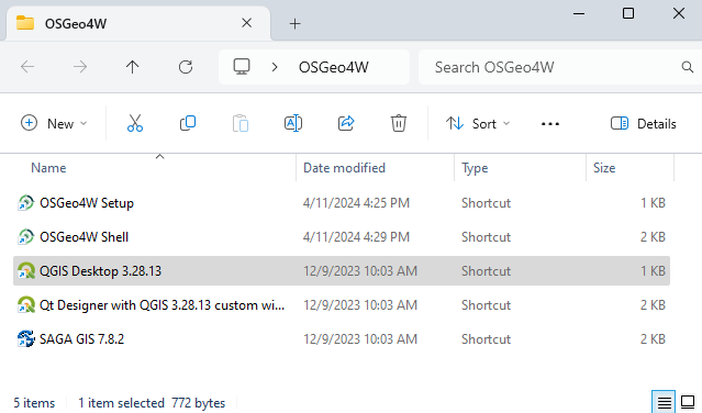
Search the start menu and run the “QGIS Desktop” program.
Complete Lesson 2 prior to starting this lesson.
Save the project
Step 2: Import data#
Start by cleaning up the map space so the next layer will be easy to see.
Uncheck the User Left Bank Lines, Right Bank Lines, and Cross Sections layers;
Uncheck the Blocked Areas;
Uncheck the Storm Drain User Layers;
Click the User Boundary Conditions Layer to activate this layer;
Drag the Hydraulic Structures onto the map space.
Note
If the image is blurry, use Firefox or open the image in a new tab.
Step 3: Format the data layers#
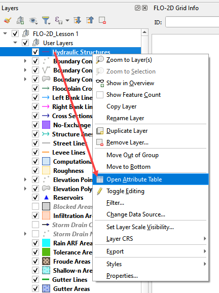
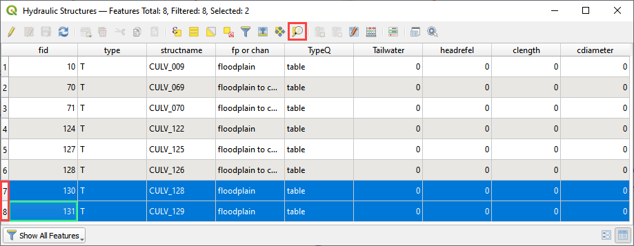
Open the Attributes Table on the Hydraulic Structures Layer.
Select structure 130, and 131 and click Zoom map to selected rows button. This will zoom the map to these two structures.
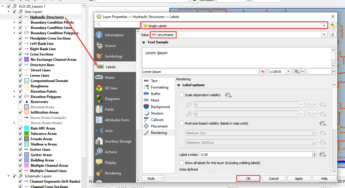
Label the Hydraulic Structures layer.
Double click the Hydraulic Structures layer
Set the Labels like the following image.
This shows which culvert is being reviewed.
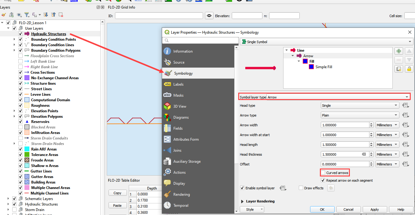
Change the layer Symbology
Change the tab to Symbology
Set the Symbol Layer Type to Arrow
Uncheck Curved Arrows
This shows the flow direction of each structure.
Step 4: Build the culverts into the User Layers Structure Lines#
Use the Structure Editor to add all of the new structures.
Digitize all of the structures.
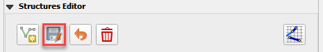
Click the Save icon to confirm that close the digitizing tool and load the data.
Digitizing process:
Left click the inlet node (upstream node)
Left click the outlet node (downstream node)
Right Click to finish the polyine.
Click OK to finish the feature.
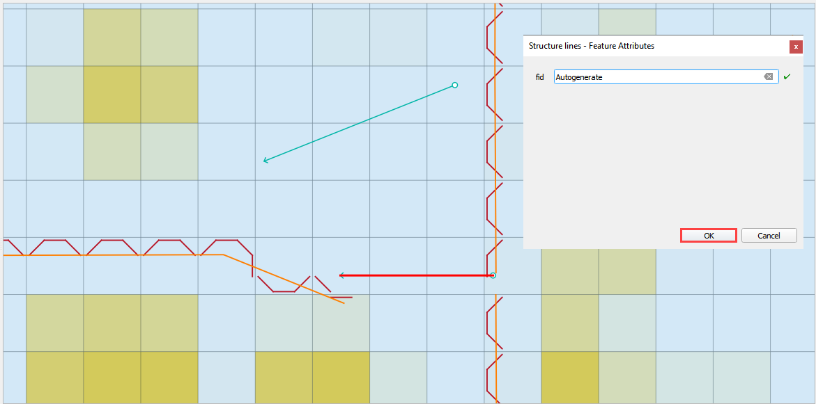
Click Save in the Structures Widget to load the data into the dialog box.
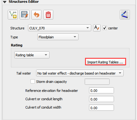
Step 5: Assign the structure attributes#
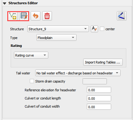
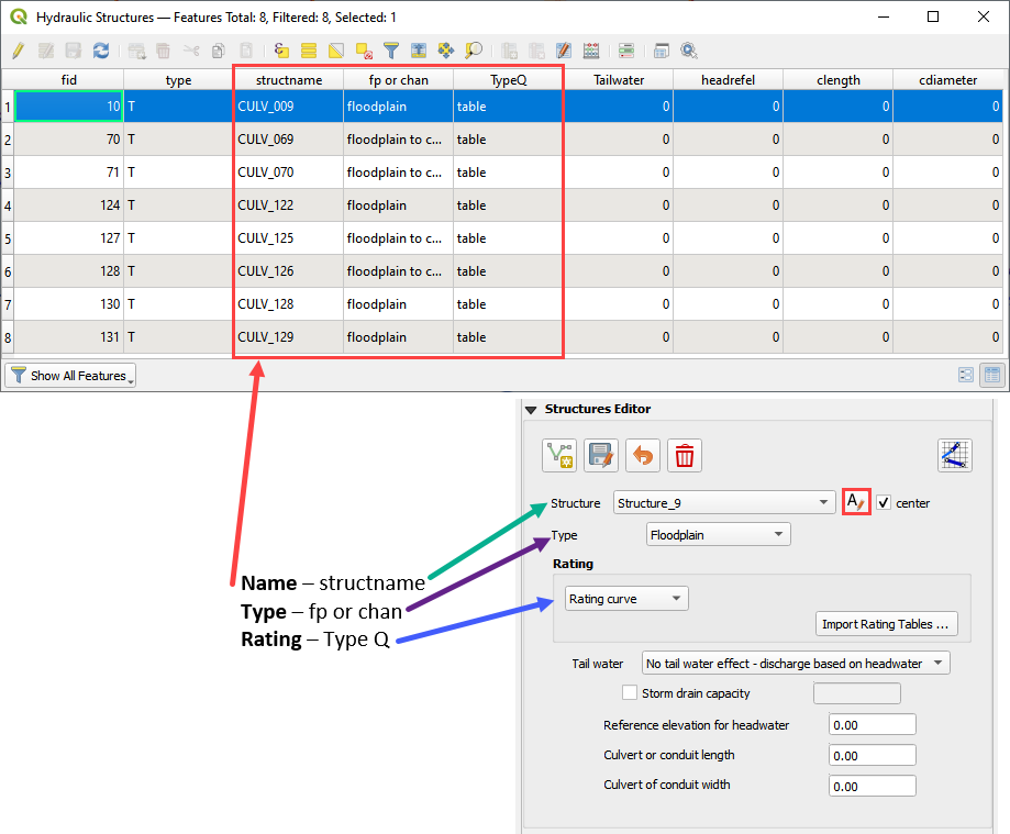
Complete the Structure Fields
Load the Hydraulic Structures Attribute table. The attributes will help fill out each structure table.
Check the center button.
Select the first structure.
Rename the Structure with the “A” button.
Fill the Type and Rating fields
Move to the next structure and repeat the process.
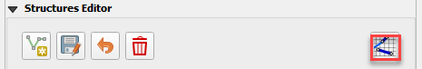
Schematize the structure data.
Step 6: Assign the rating tables#
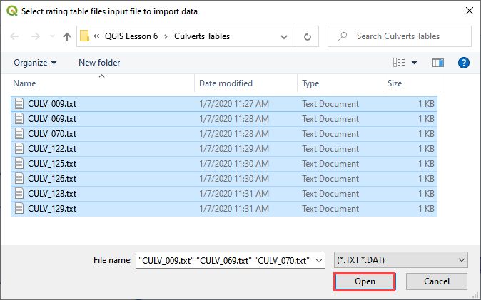
Click the Import Rating Tables button
Select the rating tables from the project folder.
Click open.
C:\Users\Public\Documents\FLO-2D PRO Documentation\Example Projects\QGIS Tutorials\QGIS Lesson 6\Culverts Tables
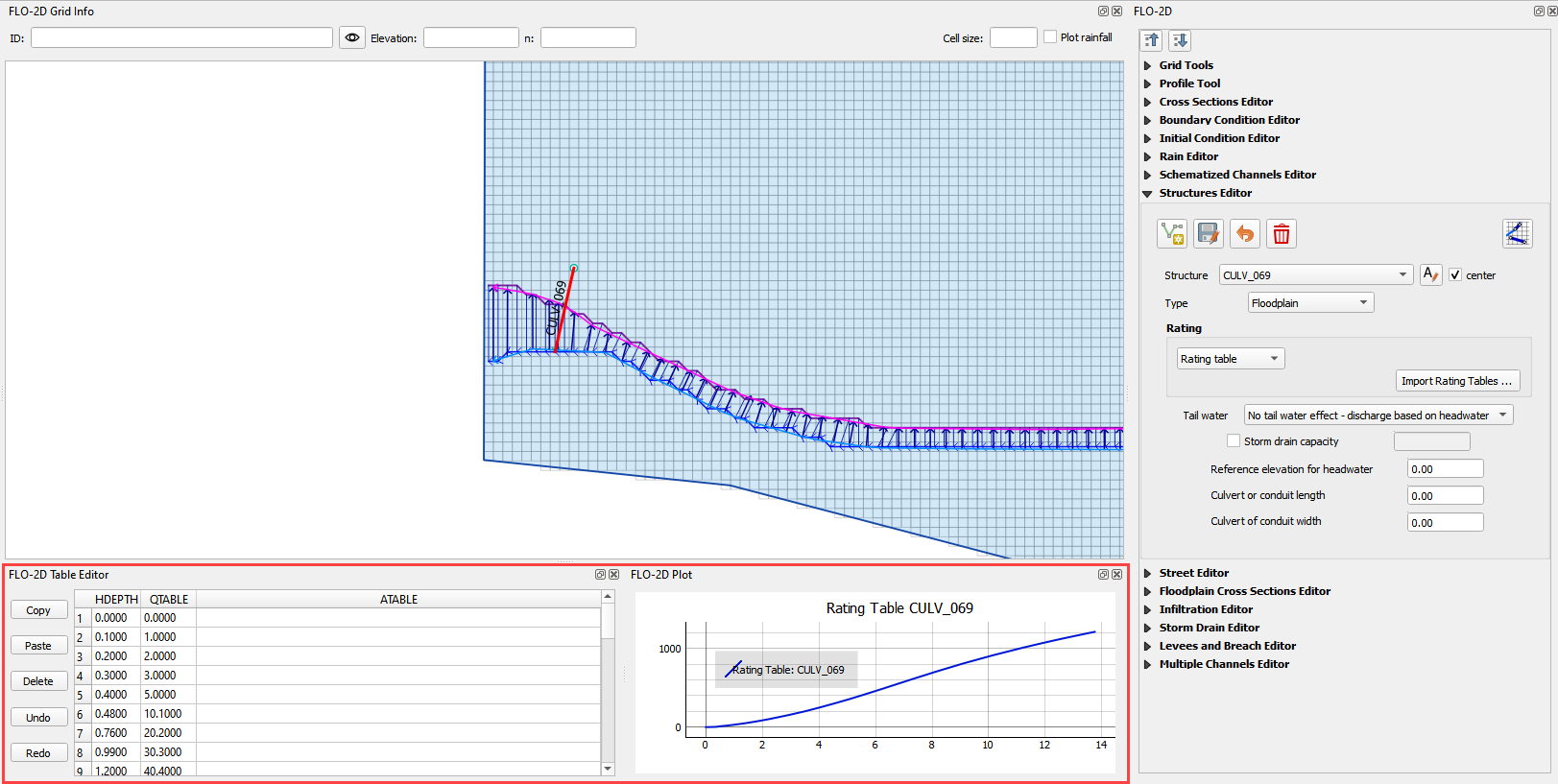
The data has been imported. Switch to another structure in the list if the table and plot does not update.
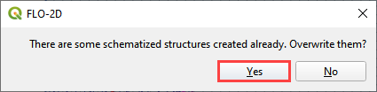
Step 7: Schematize the data#
Schematize the structure data and click Yes to replace the data.

Step 8: Export the data#
This is a good point to save project.

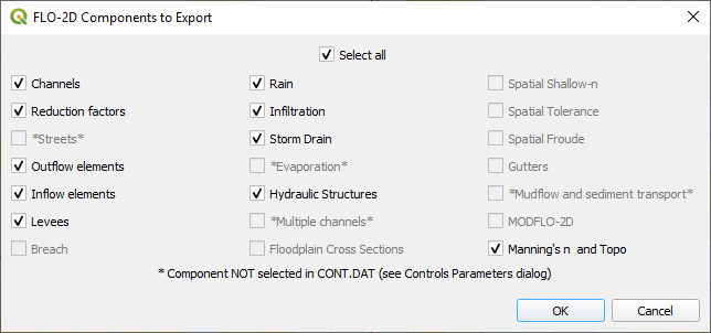
Export the data files to the Project Folder in QGIS Lesson 6 Export.
C:\Users\Public\Documents\FLO-2D PRO Documentation\Example Projects\QGIS Tutorials\QGIS Lesson 6\Lesson 6 Export
All GDS data files will be created in the selected project folder.
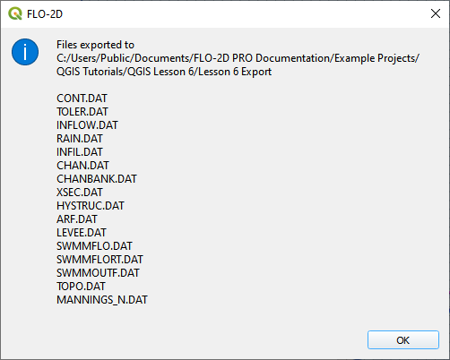
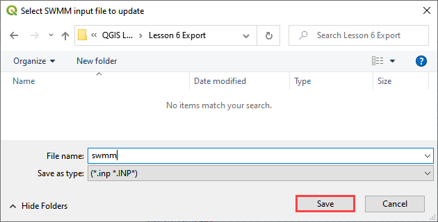
The swmm.inp file was not exported. Copy it from Lesson 3 Export folder or export it again using the Storm Drain Editor.
Step 9: Run the simulation#
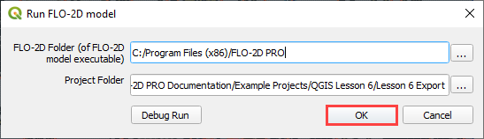
Click the Run FLO-2D Icon.
Set the Project path and the FLO-2D Engine Path and click OK to start the simulation.