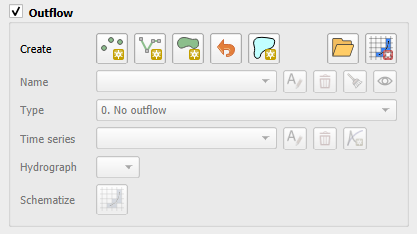
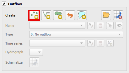
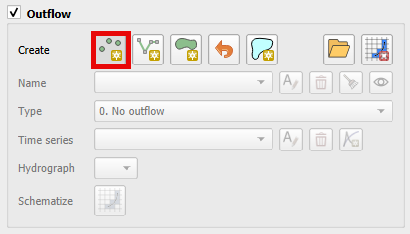
Outflow Editor#
Boundary outflow conditions include:
Normal Depth Control
Time Stage Control
Discharge Stage Control
Multiple Domain Exchange
These conditions define how the channel or floodplain discharge enters or leaves the FLO-2D model domain.
Normal#
Outflow Floodplain#
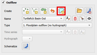
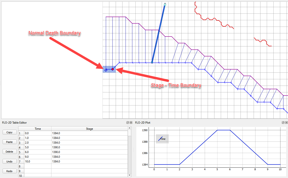
Normal depth boundary
This is an outflow condition where the flow leaves the domain without effecting the upstream water surface elevation, select the outflow nodes along the downstream boundary or along the edge of a grid system.
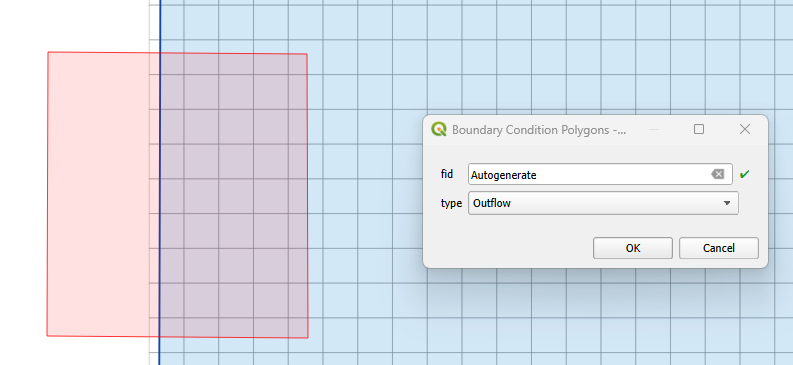
Click the Add Polygon BC button

Digitize a polygon that covers the desired boundary extent. Right click the last vertex to close the polygon.
Set the type to Outflow and click OK.
Click again the toggled Add Polygon BC button to save the feature and activate the editor.
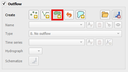
Name the boundary and set the outflow type to 1. Floodplain outflow (no hydrograph).
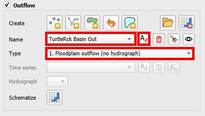
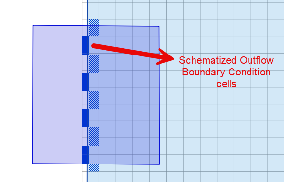
Click the Schematize button (shown below) to complete the boundary.
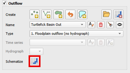
The Add Polygon BC button will identify cells at the grid boundary and designate them as outflow cells.
Tip
It is possible to set the Outflow Boundary Conditions to the whole grid boundary cells faster using the Add Outflow Boundary Condition to the whole grid boundary cells button.
The algorithm in this button is more efficient than the Add Polygon BC. However, This boundary method applies a normal depth boundary to every grid element on the outer edge of the computational domain.
A line is added to the center of the cells on the boundary of the grid.
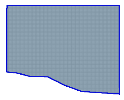
Modification of the line is possible as needed.
When the schematize button is clicked, the whole boundary grid cells are defined as normal depth.
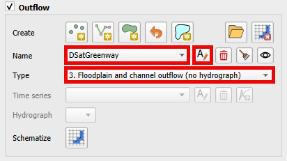
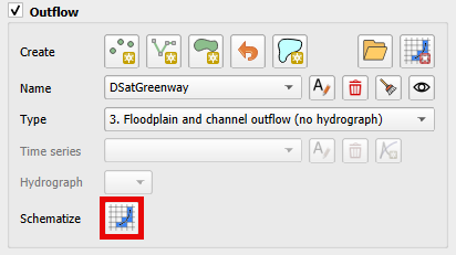
Outflow Channel#
For channel outflow at a normal depth condition, use the channel outflow node on the downstream boundary or channel segment terminus.
Click add a point boundary
Click the last left bank channel node.
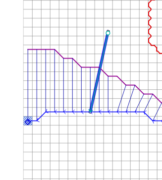
Click again the toggled Add Point BC button to save the feature and activate the editor.
Name the feature and set the outflow condition for the channel to 3. Floodplain and channel outflow (no hydrograph).
Note
One point is required.
Click the Schematize button.
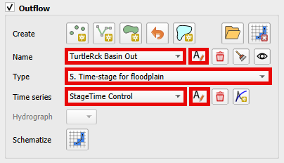
Time Stage Control#
Outflow with Time – Stage Hydrograph for Floodplain#
To represent variable time-stage boundary conditions such as:
Tides
Storm surge
Tsunamis
Flooding from a large river
The time–stage relationship can be synchronized with rainfall and upstream watershed flooding. Select the outflow nodes along the downstream boundary with a polygon.
Click the Add Polygon BC button.
Digitize the polygon across the boundary.
Click again the toggled Add Point BC button to save the feature and activate the editor.
Name the boundary, set the boundary conditions, name and fill the Time Series table.
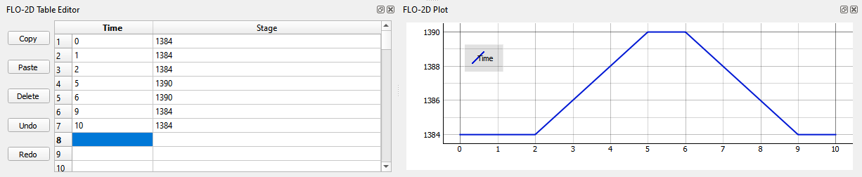
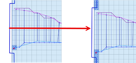
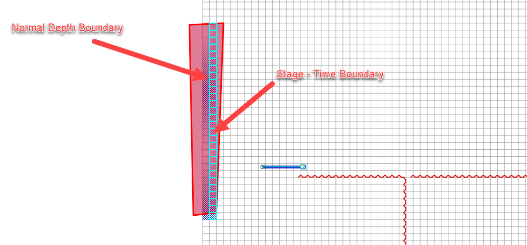
In the figure below, there are two sets of outflow nodes. The Normal Depth nodes allow water that exceeds the Stage to cross the outflow boundary. This allows rainfall accumulation or inflow hydrograph accumulation to leave the boundary. The Stage – Time nodes apply a water surface elevation. This water can fill the downstream area up to the stage.
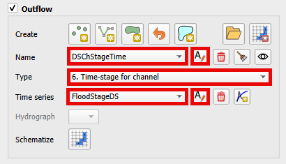
Outflow with Time – Stage Hydrograph for Channel#
Like the time-stage condition for the floodplain select this option to represent ocean tide, storm surge, tsunamis, or flooding from a large river control in a channel terminus. The time – stage relationship can be synchronized to rainfall and watershed flooding.
Select the standard outflow node at the end of the channel.
Set the time-stage node one element upstream.
Click again the toggled Add Point BC button to save the feature and activate the editor.
Name the boundary and set the boundary conditions.
Name and fill the Time Series table.
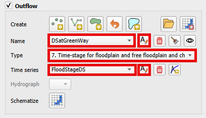
Time-Stage for Floodplain and Free Floodplain and Channel#
Use this option to set the stage of a downstream elevation control. This node will allow water to collect on the boundary until it can exceed the stage at the boundary. It can be used for two purposes.
Anytime there is a control on the boundary that releases water at a known stage.
Set the elevation for matching the water surface elevation of an existing FEMA map.
Set this up with the same method described in the previous two sections.
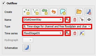
Time-Stage for Channel and Free Floodplain and Channel#
This option is the same as option 7 with the condition that the stage – time table is assigned to the channel instead of the floodplain.
Set this up with the same method described in the previous two sections.
Discharge Stage Control#
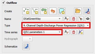
Channel Stage-Discharge Parameters#
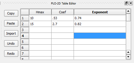
This outflow option defines the discharge from a channel based on the stage using rating curve. Several rating curves can be assigned for multiple limiting depths. This system is used when there is a control or a gage at the channel with a known stage-discharge relationship.
Select the stage-discharge node at the end of a channel segment.
Click again the toggled Add Point BC button to save the feature and activate the editor
Name the boundary and set the boundary conditions.
Name and fill the Q(h) parameters table.
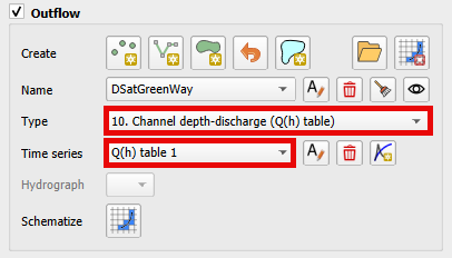
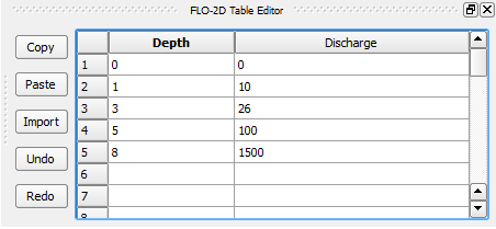
Channel Stage-Discharge (Q(h) table)#
The final outflow option is used to define the downstream boundary with a stage-discharge table.
Select the stage-discharge node at the channel terminus.
Click again the toggled Add Point BC button to save the feature and activate the editor
Name the boundary and set the boundary conditions.
Name and fill the Q(h) table.
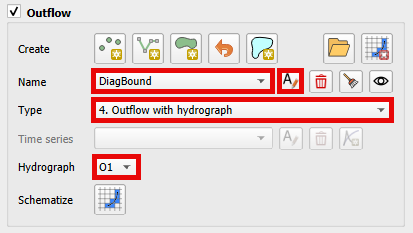
Multiple Domain System#
Use this option with any floodplain boundary that will transfer flow between two domains.
Click the Add Polygon BC button.
Draw a polygonn through the desired outflow nodes.
Click again the toggled Add Point BC button to save the feature and activate the editor.
Name the boundary condition and set the boundary Outflow type conditions as Outflow with Hydrograph.
Click the Schematize button.
Troubleshooting#
The most common problems with creating outflow.dat data is caused by creating conflicts by putting other components in the outflow grid elements.
The schematic layers and tables will reset each time the Schematize tool is used. This could cause overwriting of imported data. Convert the Boundary Conditions to User Layers for projects that are imported into QGIS before performing the schematization process.
If the data does not export correctly, check the tables. The tables can be edited directly or can be copied into an OUTFLOW.DAT file.
Saving and restarting might resolve some issues with the GeoPackage but check the layers attributes prior to restarting QGIS.
If a Python Table Update error appears, Delete the QGIS folder from AppData/Roaming and rebuild the QGIS Profile.