
Initial Condition Editor#
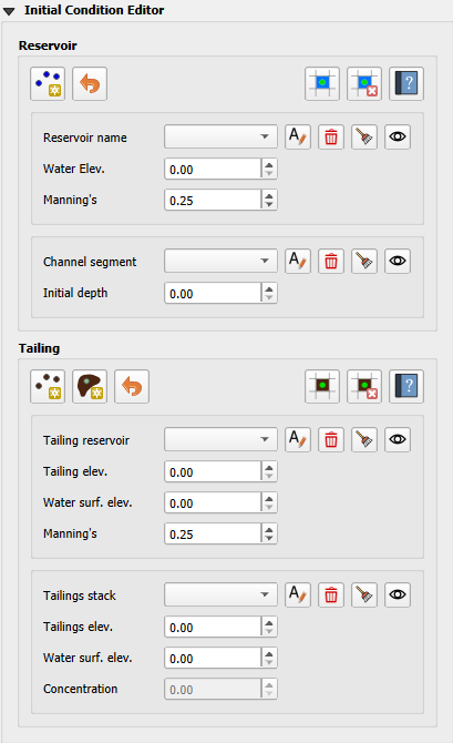
The Initial Condition Editor is used to set the FLO-2D Initial conditions. This editor is used to set the following initial conditions:
Reservoirs
Channel Initial Depth
Tailings Stack
Important
The available groups depend on the simulation settings. The previous image illustrates a two-phase simulation, where both a clear water reservoir and a tailings reservoir can be modeled simultaneously. However, if the simulation is set to clear water only, only the water reservoir will be displayed to the user. Conversely, if the simulation is set to mudflow, only the tailings group will be shown.
Initial Condition Outline#
The Initial Condition Editor is a tool designed to generate the .DAT files required for different types of simulations. Depending on the configuration of the switches, the editor exports specific files customized to the selected simulation type.
The flow chart below outlines the logic for exporting .DAT files based on the switches’ selection:
        graph TD

     E[INFLOW.DAT] --> |Clear Water|A[MUD = 0 <br/> ISED = 0]
     E[INFLOW.DAT] --> |Mudflow|B[MUD = 1 <br/> ISED = 0]
     E[INFLOW.DAT] --> |Sediment Transport|C[MUD = 0 <br/> ISED = 1]
     E[INFLOW.DAT] --> |Two-Phase|D[MUD = 2 <br/> ISED = 0]

     I[TAILINGS.DAT] --> |Mudflow XCON = 0|B[MUD = 1 <br/> ISED = 0]

     G[TAILINGS_CV.DAT] --> |Mudflow XCON = 0|B[MUD = 1 <br/> ISED = 0]

     H[TAILINGS_STACK_DEPTH.DAT] -->  |Two-Phase|D[MUD = 2 <br/> ISED = 0]
Reservoirs Overview#
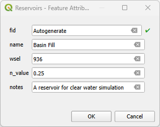
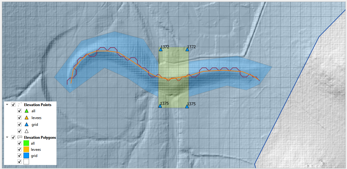
The reservoir node is used to assign the water surface elevation for a reservoir or pond by specifying a single reservoir node elevation. The FLO-2D engine model will find a reservoir node in INFLOW.DAT and assign the fill elevation to any collected grid elements that have a lower elevation behind a levee.
The reservoir group is shown in the situations shown on the flow chart bellow:
        graph TD

     A[Reservoir Group] --> |Clear Water|B[MUD = 0 <br/> ISED = 0]
     A[Reservoir Group] --> |Sediment Transport|C[MUD = 0 <br/> ISED = 1]
     A[Reservoir Group] --> |Two-Phase|D[MUD = 2 <br/> ISED = 0]
Create a Reservoir Node#
The reservoir data is written to the INFLOW.DAT file.
Click the Reservoir button.

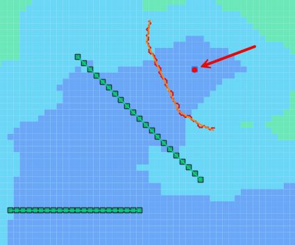
Click a grid element within the reservoir.
Set the name and elevation.
Click again on the Reservoir button to finish the editing. It is grey when on editing mode.

Click Schematize to save the data to the schematic layers.

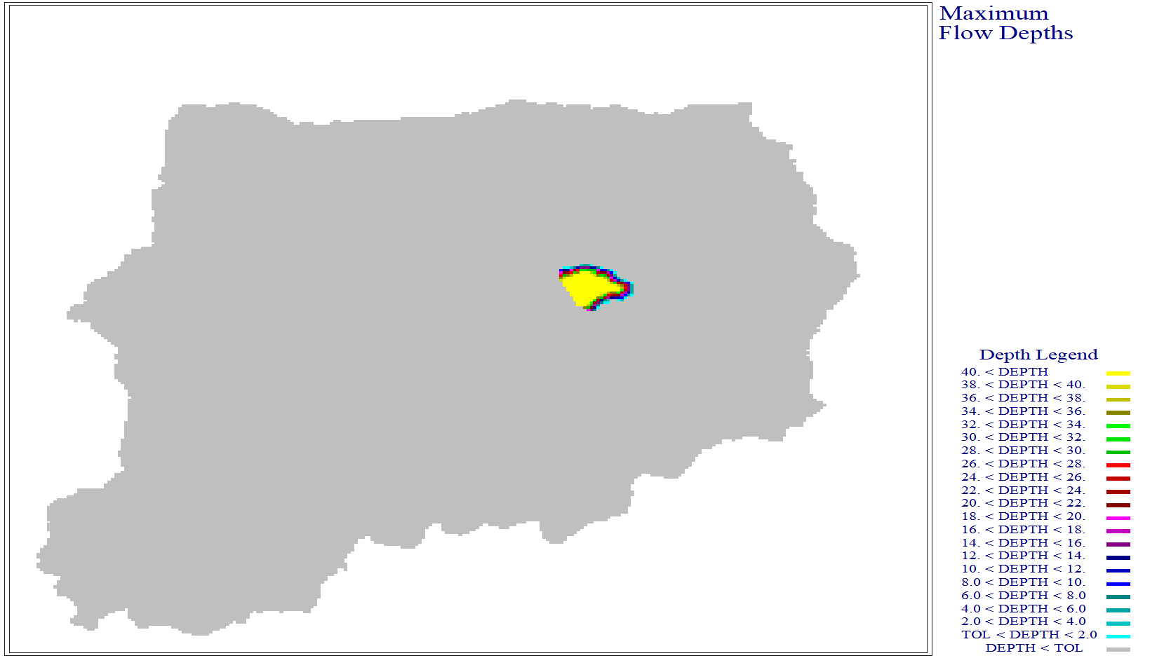
Run a fill test with graphics mode on for 0.01 hours to see if the reservoir leaks. Quick run works well for this.
Reservoir Troubleshooting#
The most common issue encountered with this tool is low reservoir bank elevation surrounding the reservoir. If the confining reservoir bank element is lower than the reservoir elevation, the water will spill out of the cell. Check the reservoir containment by running the FLO-2D simulation for short duration of 0.01 hours. The reservoir will be filled and display any leaks in the maximum depth output files.
Tailings Overview#
The tailings node is used to assign the mudflow surface elevation for a reservoir by specifying a single tailings node elevation. The FLO-2D engine model will find the tailings reservoir node in INFLOW.DAT and assign the fill elevation to any collected grid elements that have a lower elevation behind a levee.
The tailings polygon is used to assign the mudflow depth for a tailings reservoir by specifying a tailings surface elevation. The difference between the assigned tailings surface elevation and the grid elevation will be the depth considered on the TAILINGS.DAT, TAILINGS_CV.DAT, and TAILINGS_STACK_DEPTH.DAT.
The tailings group is shown in the situations shown on the flow chart bellow:
        graph TD

     A[Tailings Group] --> |Mudflow|C[MUD = 1 <br/> ISED = 0]
     A[Tailings Group] --> |Two-Phase|D[MUD = 2 <br/> ISED = 0]
Create a Tailings Node#
The tailings reservoir data is written to the INFLOW.DAT file.
Note
It is possible to assign either reservoirs (tailings or water) or tailings polygons, but not both simultaneously. The FLO-2D engine can only read either the INFLOW.DAT file or the TAILINGS_*.DAT files.
Click the Tailings Reservoir button.

Click a grid element within the reservoir.
Set the name and elevation.
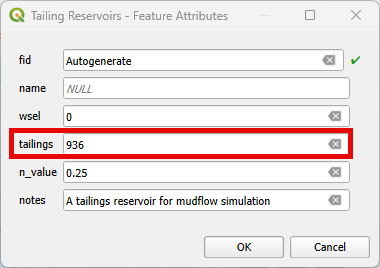
Click again on the Tailings Reservoir button to finish the editing. It is grey when on editing mode.

Click Schematize to save the data to the schematic layers.

Run a fill test with graphics mode on for 0.01 hours to see if the tailings reservoir leaks. Quick run works well for this.
Tailings Reservoir Troubleshooting#
The most common issue encountered with this tool is the same as the clear water reservoir: low reservoir bank elevation surrounding the reservoir. If the confining reservoir bank element is lower than the reservoir elevation, the water will spill out of the cell. Check the reservoir containment by running the FLO-2D simulation for short duration of 0.01 hours. The reservoir will be filled and display any leaks in the maximum depth output files.
Create a Tailings Polygon#
The tailings polygon data is written to the TAILINGS.DAT, TAILINGS_CV.DAT, or TAILING_STACK_DEPTH.DAT file depending on how the editor is set.
TAILINGS.DAT#
This file is used for simulating tailings dam material with no uniform depth.
Click the Tailings Polygon button.

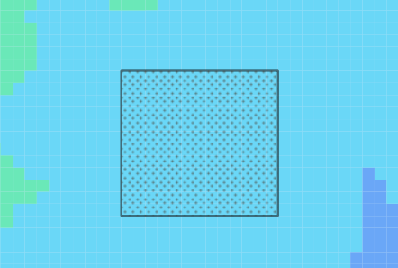
Draw a polygon representing the tailings area and click again on the Tailings Polygon to finish the editing. Add information to only the tailings_surf_elev.
Check the non-schematized Tailings Polygon.
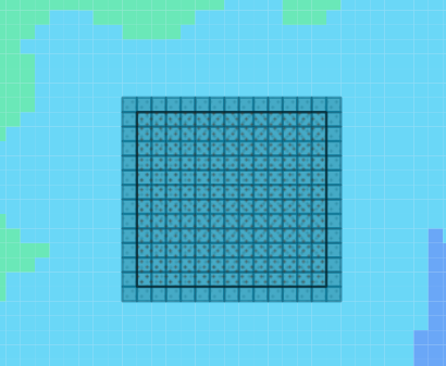
Hit the schematize buttton.

Check the schematized Tailings Polygon.
The Tailings Stack will start to move as soon as the simulation starts. Run a test with graphics mode on for 0.01 hours to check it. Quick run works well for this.
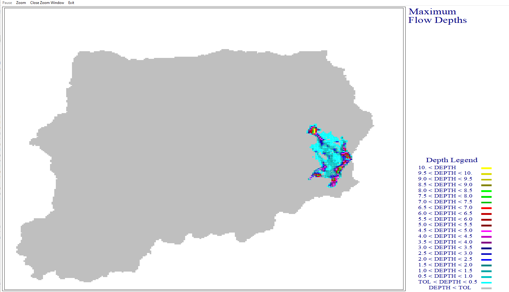
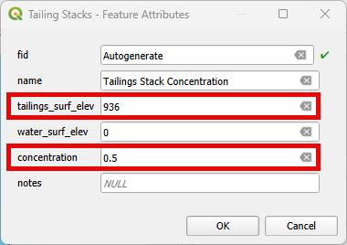
TAILINGS_CV.DAT#
This file is used for simulating tailings dam material with no uniform depth and assigns sediment concentrations to each FLO-2D grid cell.
Click the Tailings Polygon button.
Draw a polygon representing the tailings area and click again on the Tailings Polygon to finish the editing. Add information to the tailings_surf_elev and concentration.
Check the non-schematized Tailings Polygon.
Hit the schematize buttton.
Check the schematized Tailings Polygon.
The Tailings Stack will start to move as soon as the simulation starts. Run a test with graphics mode on for 0.01 hours to check it. Quick run works well for this.
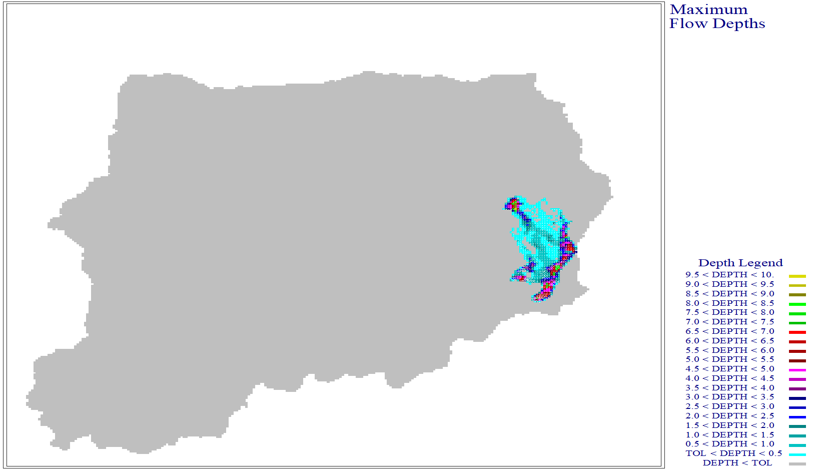
TAILING_STACK_DEPTH.DAT#
This file is used for simulating two-phase tailings dam material with no uniform depth.
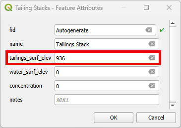
Click the Tailings Polygon button.
Draw a polygon representing the tailings area and click again on the Tailings Polygon to finish the editing. Add information to the tailings_surf_elev and water_surf_elev.
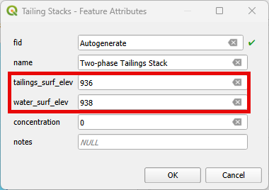
Note
The water surface elevation must always be greater than the tailings surface elevation.
Check the non-schematized Tailings Polygon.
Hit the schematize buttton.
Check the schematized Tailings Polygon.
The Tailings Stack will start to move as soon as the simulation starts. Run a test with graphics mode on for 0.01 hours to check it. Quick run works well for this.
Note
If the TAILINGS_STACK_DEPTH.DAT file is located in the same folder as the other .DAT files, the INFLOW.DAT is not required. Make sure to turn off LEVEE on CONT.DAT.
        graph TD
     A[Tailings Dam Failure] --> B[Static?]
     A --> C[Hydrologic?]
     A --> D[Seismic?]
     C --> E[Developing]
     D --> E
     E --> F[Test and Review]
     F --> G[Is it successful?]
     G -->|Yes| H[Implement]
     G -->|No| I[Iterate]
     I --> C
     H --> J[Finish]
Elevation Correction#
Before filling a reservoir, it is usually necessary to cut the ground or water elevation from the grid. This can be performed with raster cut tools or Civil 3D surface editor tools.
Example 1 - The Digital Elevation Model (DEM) for this reservoir includes the dam and water surface.
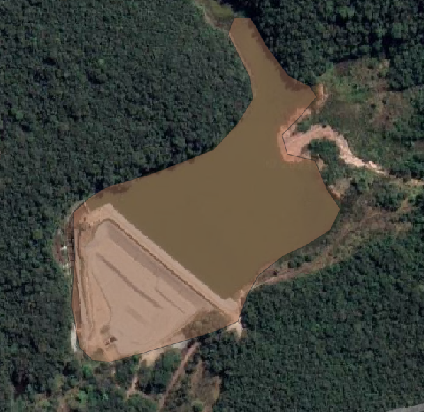
Example 2 - The DEM for this basin includes the dam but not the water.
It is necessary to remove the dam or reservoir elevation from the grid system so it can be filled with water and tailings using the initial condition reservoir node.
There are several tools available for performing this task.
The FLO-2D plugin has an elevation raster processing tool that can cut a dam and reservoir or tailings storage facility from a raster. PreProcessing Tool.
The Elevation Correction Tool can remove dam elevation directly from the grid. Grid Elevation Correction Tool.
The QGIS Serval Plugin also has a nice cut and fill tool that is an elegantly simple way to cut and fill any raster. Load that plugin using the Plugin Manager.
Once the grid elevation is corrected, the project is ready for a reservoir node.
Channel Segment Initial Depth#
Use this option to set an initial depth in any channel segment. The water depth will be assigned to every channel cross section within the segment at runtime. The initial condition will be written to the CHANNEL.DAT file.
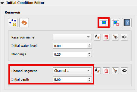
Select the channel segment.
Set the initial depth.
Click Schematize to save the data to the schematic layers.
Channel Initial Troubleshooting#
The simplicity of this tool makes it simple to adjust. It is not necessary to use the tool here because the variable can also be set in the Schematized Channels Editor.