Cross Sections Editor#
This section will cover many of the tools available to develop channels for FLO-2D. This is not a step-by-step procedure. It is a compilation and detailed outline of the tools available and how to use them.
Note
For a channel tutorial series, please see the Gila Self-Help Tutorials.
Digitize Channels#
Elevation#
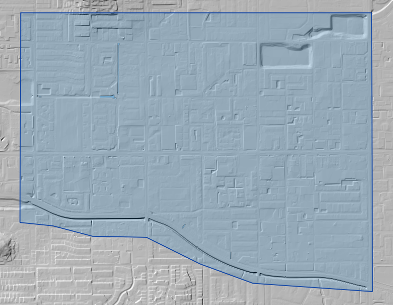
The elevation raster symbology can be edited so that the channel is well defined.
Right click on the Elevation Raster and click on properties.
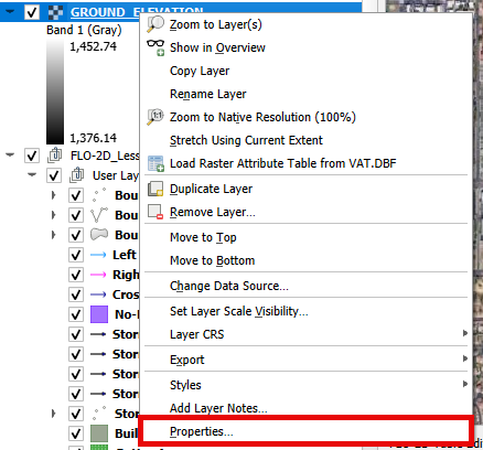
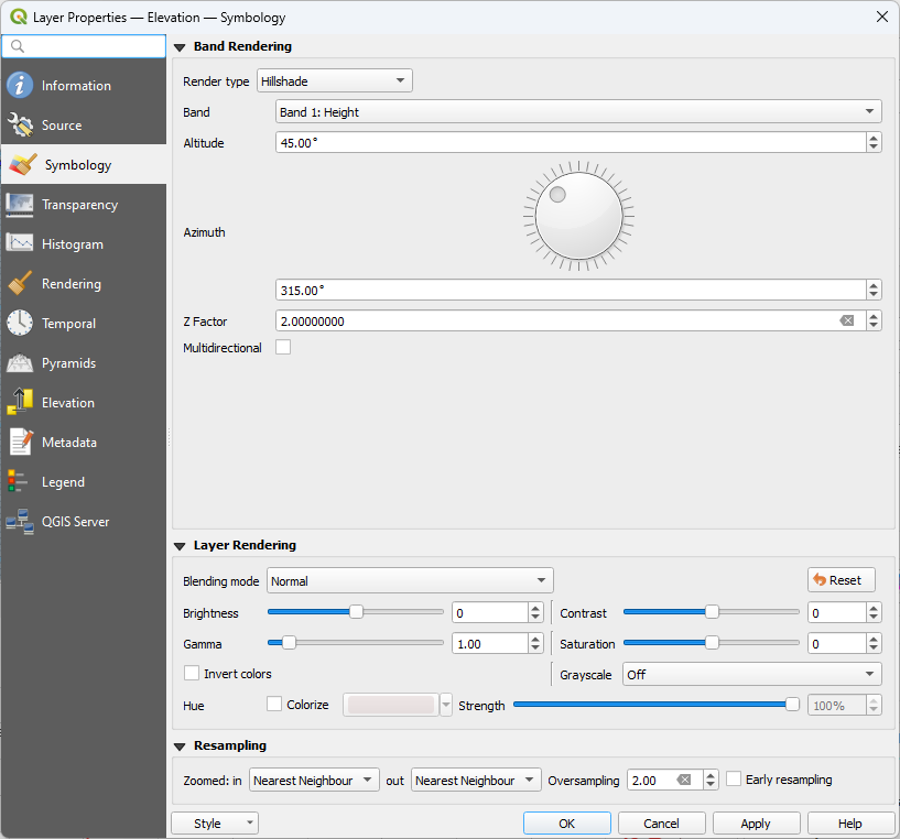
Select the Symbology tab and set the Render Type to Hillshade.
Set the Z scale to 2.
Digitize Banks#
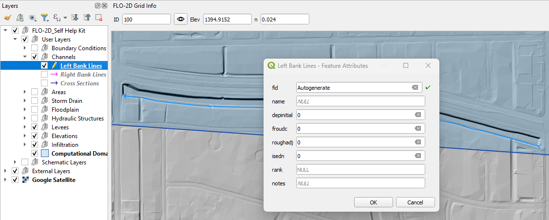
Left Bank#
Select the Left Bank Line layer.
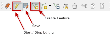
Click on both the start editing button and the add feature button.
Create a polyline to represent the left bank looking downstream and click to save the layer.
It is important to create the segments from order upstream to downstream.
Tributaries or split channels should be created once the main channels are complete.
Repeat the process for the all the various channel segments and save.
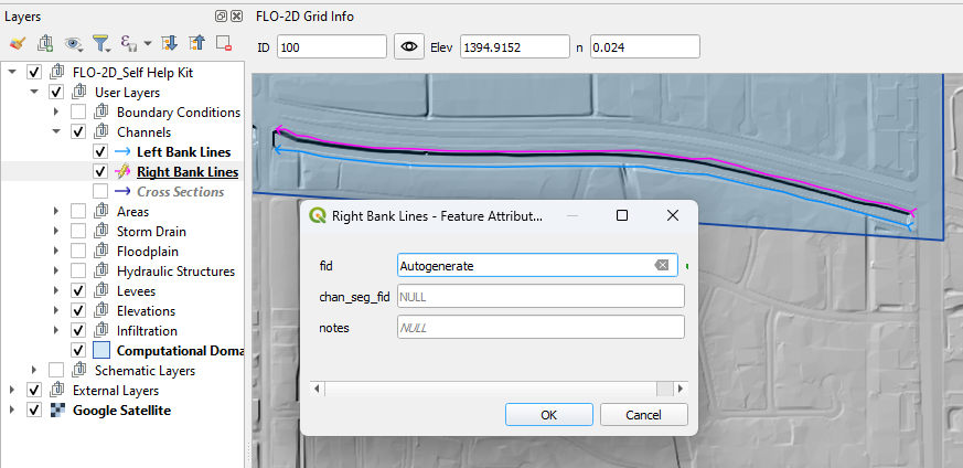
Right Bank#
Select the Right Bank Line layer.
Click on both the start editing button and the add feature button.
Create a polyline to represent the right bank looking downstream and click to save the layer.
It is important to create the segments from order upstream to downstream.
Tributaries or split channels should be created once the main channels are complete.
Repeat the process for the all the various channel segments and save.
Digitize Cross Sections#
Build Cross Sections#
To create natural cross sections, the cross sections should be numbered consecutively from upstream to downstream for each channel segment.
Note
Draw polylines from left bank to right bank looking downstream.
The first cross section must cross the left and right bank and be inside the same grid elements as the end points.
Each cross sections must cross the left and right bank.
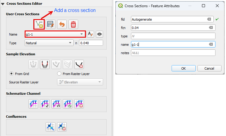
Click the Add Cross sections lines button.
Digitize the cross section on the map.
Name the cross section and click OK to finish the feature.
Click save to complete the process and load the data into the widget.
Repeat this process from upstream to down stream.
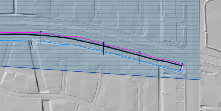
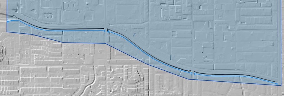
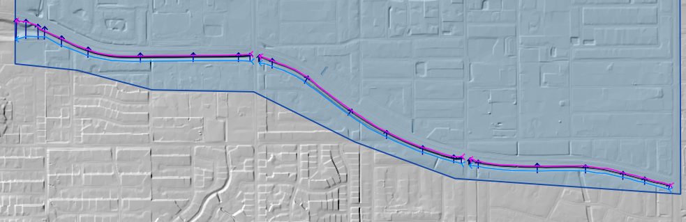
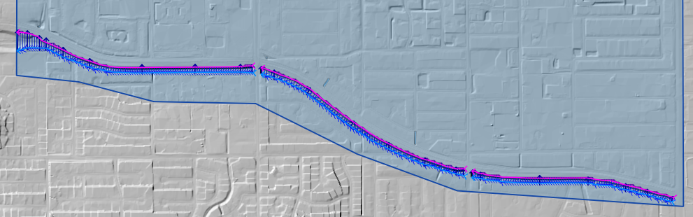
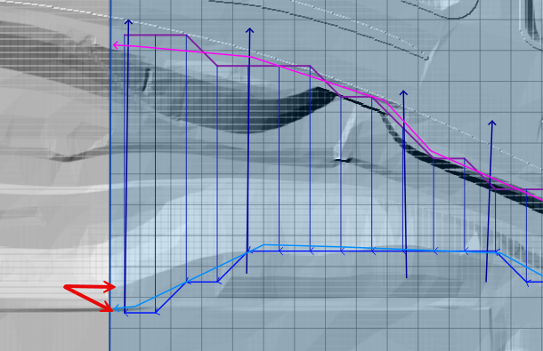
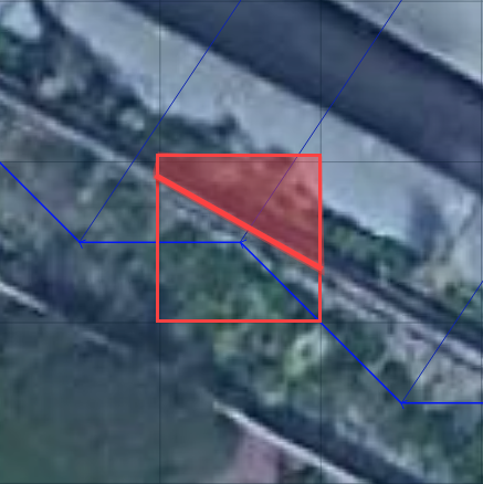
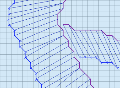
The cross sections shown in the following image have been digitized.
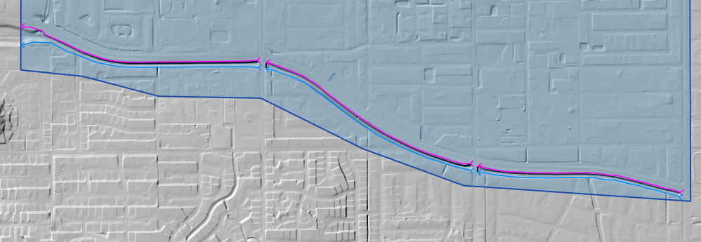
The finished product will look something like the following image.
Station Elevation#
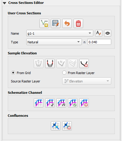
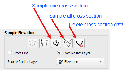
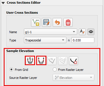
The preferred and easiest way to sample elevation data for a cross section is by using the FLO-2D Sample Elevation tool. Once the cross sections are digitized onto the map, the Sample Elevation tools are used to sample elevation data from a raster into Stations/Elevation data sets for all or individual cross sections.
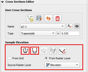
This section will focus on natural channel geometry (N type).
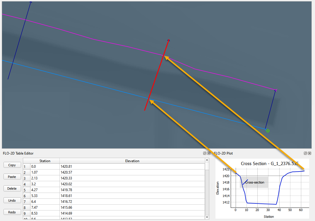
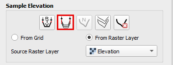
Set the elevation raster as the Source Raster Layer and use either button to sample one or all cross sections.
The station elevation data is limited to the point where the left and right bank intersect the cross section.
If too much or too little data has been sampled, adjust the left or right bank alignment and sample the elevation again.
Schematize and Interpolate#
Schematize#
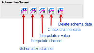
Once the banks and cross sections are complete, the next step is to Schematize the channels. Click the Schematize button.
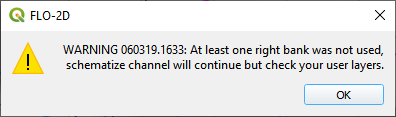
Errors and warning will appear if something is not configured correctly.
At the beginning of each segment, the left bank node, right bank node must be in the same cell as the end nodes on the cross sections.
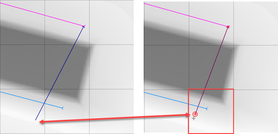
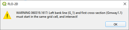
If the cross section does not touch the left or right bank, the following message will appear.
Correct this condition by making sure each cross section crosses both banks.
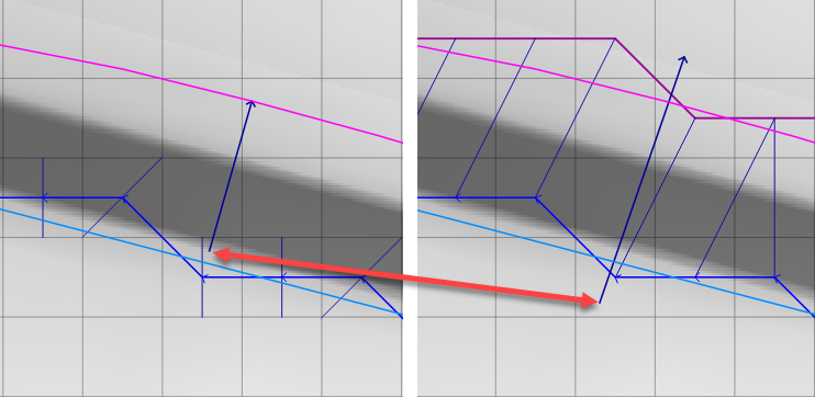
If the channel schematize process was successful, the log message panel will report the schematize information.
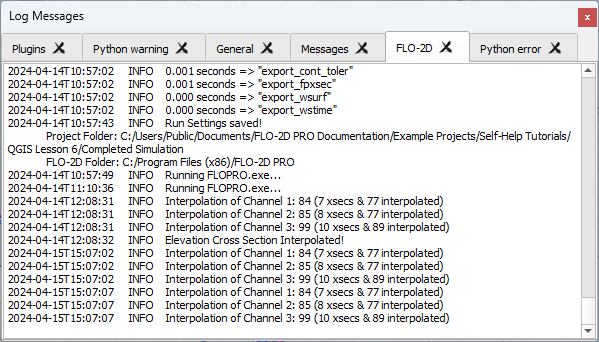
The schematized layers now have complete left bank, right bank, and cross section data.
Note
It is a good time to realign the left and right banks if they do not have good alignment.
Interpolate#
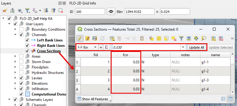
Inspect the cross section n-value field to ensure all n-values are present. If missing, fill the required n-value to the field.
Right click on the Cross Sections layer to open the Attribute Table.
Click the interpolate button to run the interpolator.
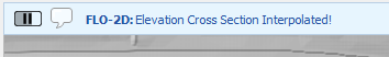
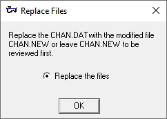
If the interpolation is performed correctly, the following message will appear.
Troubleshooting cross sections#
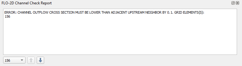
If a cross section data is bad, the interpolator will not run. An error message may appear.

Check to see if the channel width is correct by running the clicking the channel check button.
If the channel is not wide enough, a dialog box will load that allows the user to load the channel that needs to be widened.
Move the left or right bank further away from each other and run the schematize and interpolator again.
Prismatic Cross Sections#
Prismatic channel data can be entered and interpolated using the cross section editor. Use this option for creating Rectangular and Trapezoidal channel segments. This example will use two segments of channel data. One for a rectangular channel and one for a trapezoidal channel.
Rectangular Cross Sections#
Set up the Editor Widget. Type = Rectangular base n = 0.020
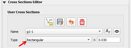
Click the create cross section button.

Draw the first cross section and enter the Feature Attributes. See Sample bank data to
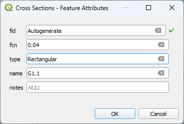
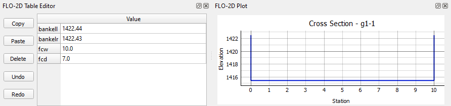
Click Save to load the cross section into the Table Editor.

Fill the bank elevation data with the sample elevation tool.
For more detailed instructions See Sample bank data.
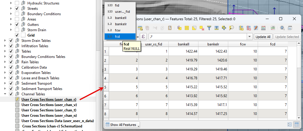
Use the table editor to fill the width and depth variables for each cross section. It is also possible to use the Attribute table editor for the Advanced Layers.
Note
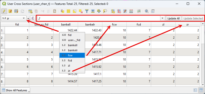
A fast way to modify the width and depth variables is to use the Advanced Layers Attribute table.
Trapezoidal Cross Sections#
Set up the Editor Widget. Type = Trapezoidal base n = 0.020
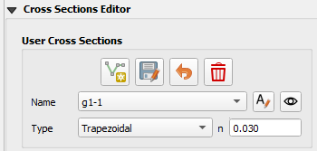
Click the create cross section button.
Draw the first cross section and enter the Feature Attributes.
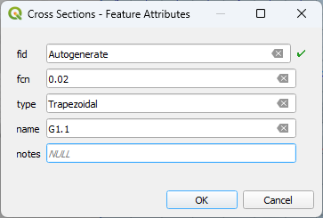
Click Save to load the cross section into the Table Editor.
Fill the bank elevation data with the sample elevation tool.
For more detailed instructions See Sample bank data.
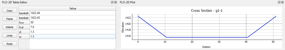
Fill the remaining width, depth, and side slope with the table editor.
It is also possible to use the attribute editor and the Advanced layere.
Note
A fast way to modify the width, depth, and side slope variables is to use the Advanced Layers Attribute table.
Schematize Prismatic#
Once the banks and cross sections are complete, the next step is to Schematize the channels. Click the Schematize button.
Errors and warning will appear if something is not configured correctly.
At the beginning of each segment, the left bank node, right bank node must be in the same cell as the end nodes on the cross sections.
If the cross section does not touch the left or right bank, the following message will appear.
Correct this condition by making sure each cross section crosses both banks.
If the channel schematize process was successful, the log message panel will report the schematize information.
The schematized layers now have complete left bank, right bank, and cross section data.
Note
It is a good time to realign the left and right banks if they do not have good alignment.
Sample Bank Data#
There are many ways to edit the bank data for R and T type channels. This section will show two different ways to create and correct bank elevation data.
The bank elevation data can be sampled in two methods.
Method 1: Elevation from Grid#
The first method is from the Grid layer and the second is from the elevation Raster.
Click the From Grid radio button and select Individual or all cross sections to sample.
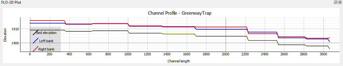
The bank data is the reference point to determine the bed elevation of the channel so it can influence the profile. For example, if one uses the grid element elevation to set the bank elevation, the channel profile is wrong. The Grid method should only be used if a good raster is not available.
Click the channel profile tool and the left bank to check the profile of the channel.
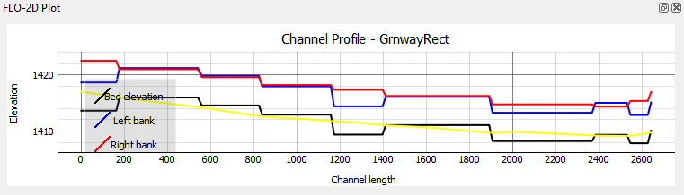
This is not the preferred method since a grid elevation for a grid is always somewhere in between the bank of the channel and the internal channel data.
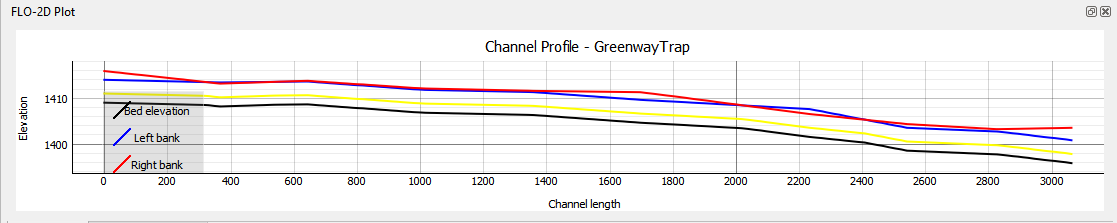
Method 2: Elevation from Raster#
This method is used if an elevation raster can be used to define the bank elevation.
Click the From Raster radio button and select Individual or all cross sections to sample.
Interpolate Prismatic#
Click the interpolate button to run the interpolator.
If the interpolation is performed correctly, the following message will appear.
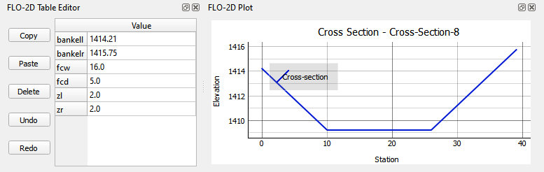
An interplated prismatic channel looks like this.
Channel n-Value Interpolator#
The channel n-value interpolator tool is used to define the n-value of a channel cross section based on the cross section geometry.
The button loads the interpolator.
The tool assigns an n-value for the chan.dat file based on the picture below.
The user can choose the n-values for a minimum or maximum cross section area.
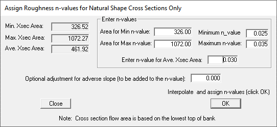
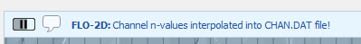
If the interpolator works, a message is displayed in the message bar.
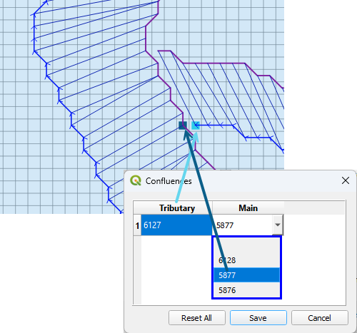
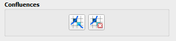
Channel Confluence Editor#
Set up confluences using the Confluence editor.
Make sure a tributary or split left bank element is adjacent to a left or right bank element of a main channel.
The confluence finder will find a list of adjacent elements that can be used for the confluence. Pick the one most likely to allow flow to exchange between the two channels.